Method and apparatus for integrated simulation

a simulation and simulation technology, applied in the field of robotic control system, can solve the problems of limited support for integrated control environment, non-homogeneous programming and maintenance environment, limited success of conventional plc/pac controller in motion planning and control, etc., and achieve the effect of less development time and convenient developmen

Active Publication Date: 2014-04-08
YASKAWA INNOVATION INC
View PDF5 Cites 3 Cited by
  • Summary
  • Abstract
  • Description
  • Claims
  • Application Information

AI Technical Summary

Benefits of technology

[0020]We submit that this invention provides an integrated simulation solution that facilitates safe and efficient development of the software control components of the complete system, including both the workcell equipment and the robot manipulator. In particular, we submit that such a method and apparatus provides performance generally comparable to the best prior art techniques while requiring less development time than known implementations of such prior art techniques while facilitating user-configurable real time feedback of data from the motion control software, whether it is connected to real hardware or to a simulator thereof.

Problems solved by technology

Furthermore, it is of no relevance in such systems which specific voltage levels are selected to represent each of the logic states.
However, due to limitations in the principle programming languages, such as that defined in IEC 6-1131, conventional PLC / PAC controllers have demonstrated only limited success in motion planning and control of robotic manipulators having multiple degrees of autonomy.
In general, robot controllers provide full kinematic support, but only limited support for integrated control environments, often being limited to use in a relatively small workcell having a limited number of I / O signals that must be monitored / managed coincident with the actual robot sensors / controls.
Such limitations arise in part due to known deficiencies in the primary controller languages, but also because the programming and maintenance environments tend to be non-homogeneous.
However, this approach is incapable of allowing the simulation to take into consideration the full range and variation of those sensory inputs that would be present in the actual instantiation.
Further, no known prior art system of this type is capable of supporting what we refer to as integrated simulation.

Method used


Image

  • Method and apparatus for integrated simulation
  • Method and apparatus for integrated simulation
  • Method and apparatus for integrated simulation

Examples


Embodiment Construction

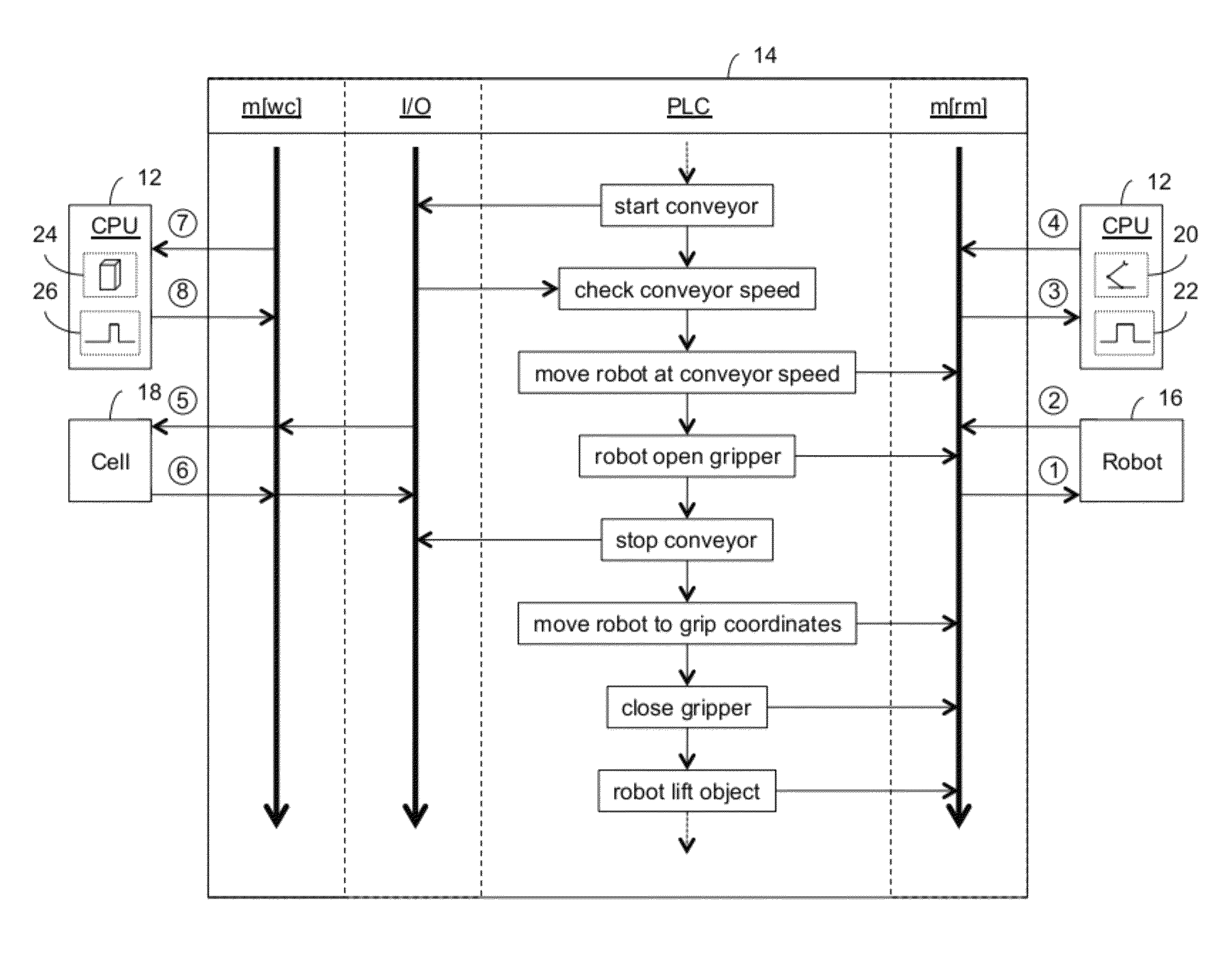
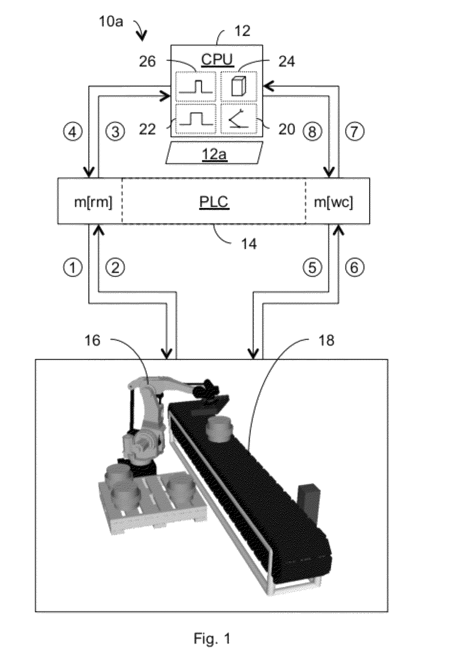
[0029]In accordance with the preferred embodiment of our invention, illustrated in FIG. 1, our integrated simulation system 10a includes a computing device 12, a programmable logic controller (“PLC”) 14, a robot manipulator 16, and a workcell 18. In general, PLC 14 comprises a plurality of controller modules, m[x]. By way of example, only the robot manipulator controller module, m[rm], and the workcell controller module, m[wc], are illustrated; however, others may be provided on an as-required basis to accommodate more complex systems. As would be expected, either the robot manipulator controller module, m[rm], or the workcell controller module, m[wc], may comprise a plurality of physical controller modules of appropriate functionality depending on the complexity of the system 10a. In addition, as is known, the PLC 14 will typically incorporate a power supply (not shown) and various communication support modules (not shown), such as Ethernet, DeviceNet, and the like.

[0030]In the ill...


PUM


Abstract

In an automated system which includes a robot manipulator, a workcell, and a control system implemented on a hardware platform based on a programmable logic controller (“PLC”), a method and apparatus for performing integrated simulation that does not require the presence of both the robot manipulator and the workcell. If one component is real, the other component is simulated so as to be sufficiently responsive to responses from the real component such that the real component is unable to discern that the other component is not also real. A computing device simultaneously displays simulacra of both the components, real and simulated, and visualizations of the responses provided by each.

Description

BACKGROUND OF THE INVENTION[0001]1. Field of the Invention[0002]The present invention relates generally to a robot control system implemented on a hardware platform based on a programmable logic controller (“PLC”) or programmable automation controller (“PAC”), and, in particular, to an integrated simulation and validation platform with a configurable data feedback system.[0003]2. Description of the Related Art[0004]In general, in the descriptions that follow, we will italicize the first occurrence of each special term of art which should be familiar to those skilled in the art of robot control systems. In addition, when we first introduce a term that we believe to be new or that we will use in a context that we believe to be new, we will bold the term and provide the definition that we intend to apply to that term. In addition, throughout this description, we will sometimes use the terms assert and negate when referring to the rendering of a signal, signal flag, status bit, or simil...

Claims


Application Information

Patent Timeline
Patent Type & Authority Patents(United States)
IPC IPC(8): G06F17/50
CPCG05B2219/23446G05B2219/32357G06F17/5009G05B2219/13174G05B2219/23453G05B19/41885G05B19/0426G06F30/20Y02P90/02Y02P90/80
Inventor KAPOOR, CHETANMARCH, PETER S.
Owner YASKAWA INNOVATION INC
Why Eureka
Try Eureka