Roller bearing backing ring assembly

a backing ring and roller bearing technology, applied in the direction of bearing unit rigid support, transportation and packaging, mechanical equipment, etc., can solve the problems of shaft or bearing failure, backing ring and journal can experience fretting wear, etc., to reduce fretting wear, increase stability, and reduce the effect of fretting wear

Active Publication Date: 2014-04-15
AMSTED RAIL CO INC
View PDF15 Cites 19 Cited by
  • Summary
  • Abstract
  • Description
  • Claims
  • Application Information

AI Technical Summary

Benefits of technology

[0005]To reduce the potential for fretting wear on journals and backing rings, an assembly is presented having increased stability to reduce fretting wear. The assembly is composed of two components: (1) a backing ring fitted on the journal and (2) a locking ring to connect with and further affix the backing ring on the journal. The locking ring has an lateral outer end engaging the backing ring and an lateral inner end adjacent to the outer diameter of the dust guard portion of the axle. The locking ring reduces axial movement in the backing ring resulting from axle deflection.

Problems solved by technology

As result of shaft deflections, the backing ring and the journal can experience fretting wear as the backing ring moves relative to the journal.
The loose backing ring accelerates wear on the bearing assembly and journal, potentially leading to shaft or bearing failure.

Method used


Image

  • Roller bearing backing ring assembly
  • Roller bearing backing ring assembly
  • Roller bearing backing ring assembly

Examples


first embodiment

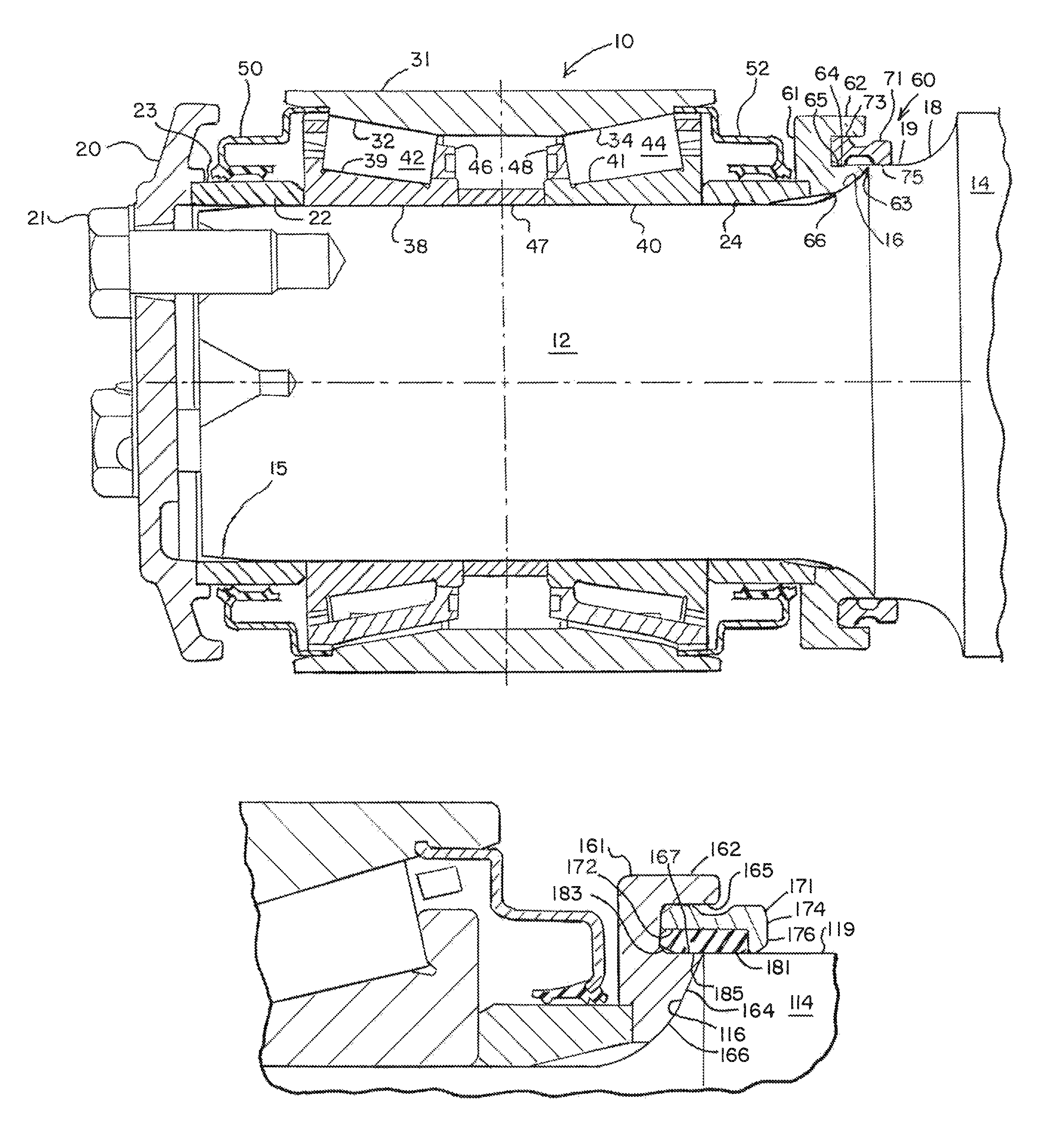
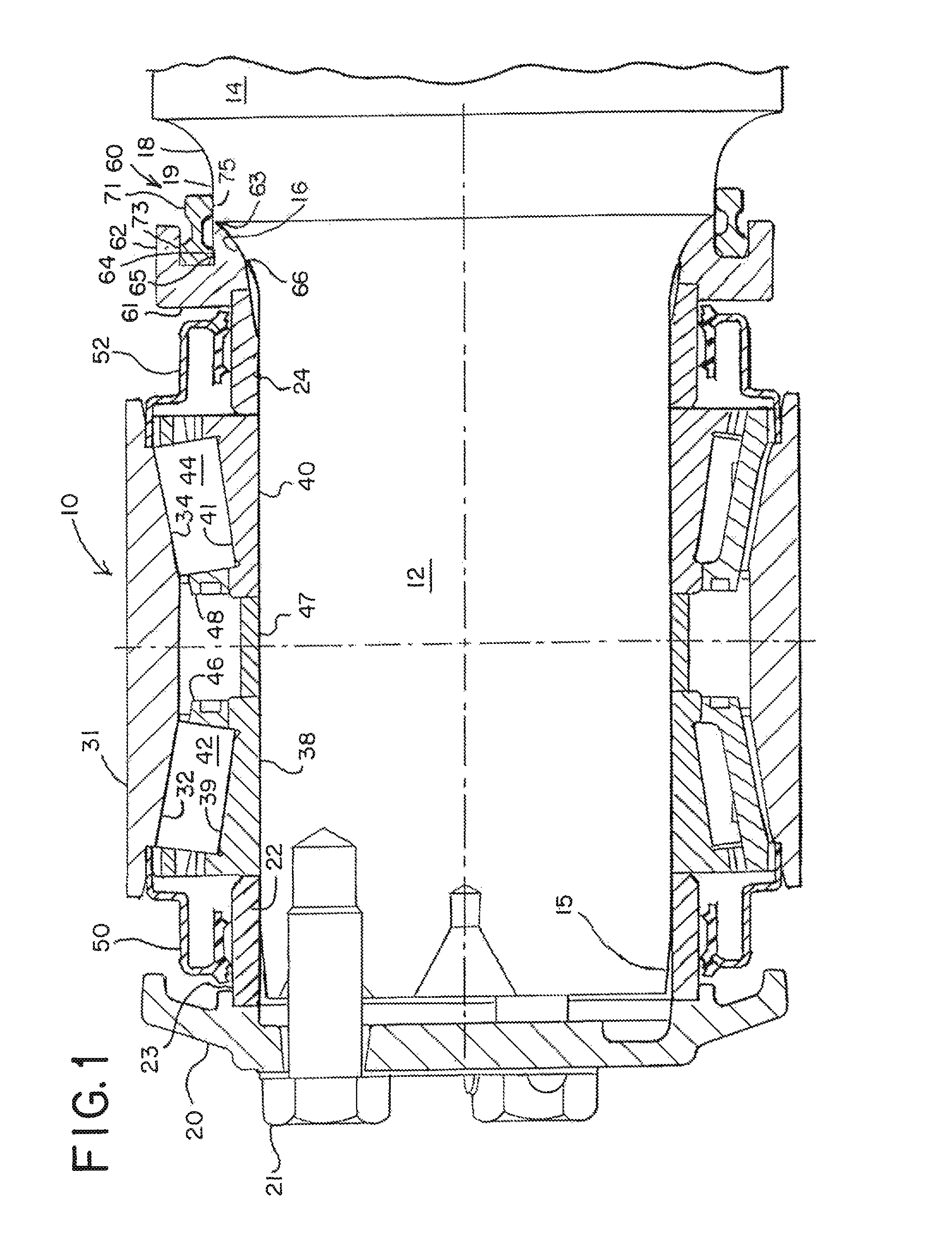
[0026]Referring to FIG. 1, the backing ring assembly of the present invention is shown. In this embodiment, the bearing assembly 10 is a tapered roller bearing of the type commonly used in railway applications to support a railcar wheel on an axle.

[0027]The bearing assembly 10 is typically preassembled before being mounted on railcar axle 14. At each free end of the axle 14, a journal 12 terminates in a slightly conical tapered section 15 to facilitate installation of the bearing assembly 10 onto the journal. The bearing assembly 10 is pressed onto the journal 12 of the axle 14 to establish an interference fit.

[0028]A dust guard 18 with a larger diameter than the journal 12 is located axially inward from the journal 12. Axially inward from the dust guard 18, the shaft 14 extends to its largest diameter. The weight of the railcar is transferred through the bearing assembly 10 to the shaft and further transferred to the rails through the railcar wheels (not shown) fitted inboard of th...

second embodiment

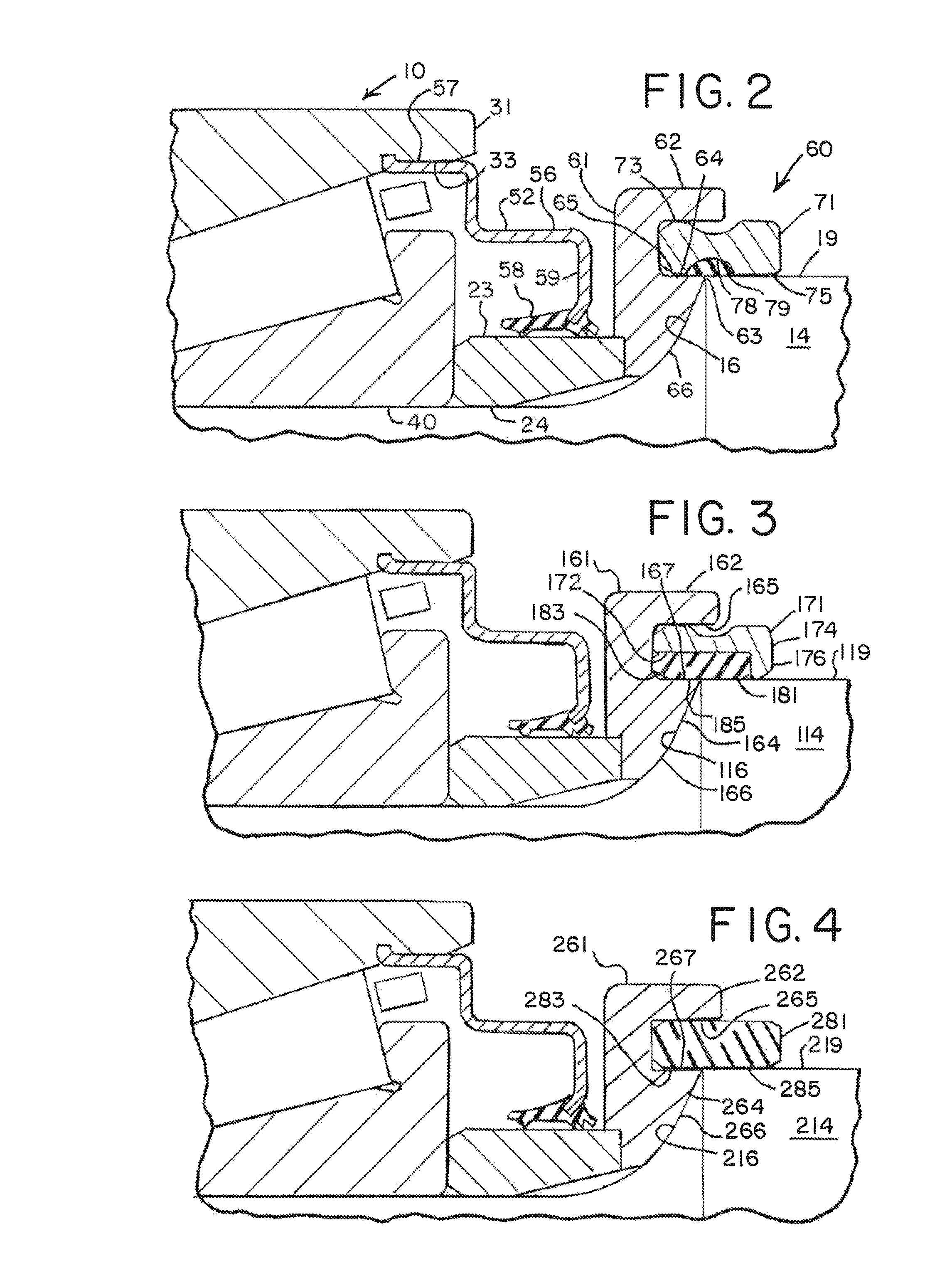
[0042]Referring now to FIG. 3, second embodiment of the backing ring assembly of the present invention is shown. Components with identical reference numerals to FIGS. 1 and 2 will not be described.

[0043]Referring now to FIG. 3, a second embodiment of the backing ring assembly is shown. Backing ring 161 is shown as a generally cylindrical, ring shape structure having a radially outer section 162 and a radially inner section 164 that together form a cutout section 165. Backing ring 161 further comprises a laterally inwardly curved face 166 which is adjacent fillet 116 of axle shaft 114. Locking ring 171 is seen as a cylindrical ring shaped structure having a laterally inner end 174 and a laterally outer end 172. Laterally outer end 172 is received into inwardly facing cutout section 165 of backing ring 161. Laterally inward end 174 of locking ring 171 is seen to include an inner radially facing 176 surface that is adjacent axle cylindrical surface 119. Resilient ring 181 is adjacent l...

third embodiment

[0044]Referring now to FIG. 4, the backing ring assembly of the present invention is shown. Components with identical reference numerals to FIGS. 1 and 2 will not be described.

[0045]Backing ring 261 is shown as a generally cylindrical, ring shape structure having a radially outer section 262 and a radially inner section 264 that together form cutout section 265. Backing ring 261 further comprises a laterally inward curved face 266 which is adjacent fillet 216 of axle shaft 214. Resilient ring 281 is adjacent to axle surface 219 and has a lateral outer end 283 fit in cutout section 265. Resilient ring has a radial inner surface 285 that is adjacent to surface 267 of backing ring 261 and axle cylindrical surface 219. Backing ring 261 is typically comprised of steel, and resilient ring 281 is comprised of a suitable polymer such as polypropylene.


PUM


Abstract

A novel assembly for a railcar axle bearing is presented. The assembly includes a backing ring affixed to the fillet of the journal of an axle and a locking ring for further affixing the backing ring the journal. The locking ring has an inboard end affixed to the dust guard of the axle and an outboard end for engaging the backing ring. The looking ring may include a resilient sealing ring.

Description

FIELD OF THE INVENTION[0001]This invention relates to roller bearings, and more particularly, to tapered roller bearings fitted on railway freight car axles.BACKGROUND OF THE INVENTION[0002]Tapered roller bearings on railcar axles support operating loads capable of producing flexural deflections in the axle, and in particular, the end portion of the axle comprising the journal on which the tapered roller bearing is affixed. The stresses imposed by the operating loads are particularly high in the journal portion of the shaft at or near the backing ring.[0003]As result of shaft deflections, the backing ring and the journal can experience fretting wear as the backing ring moves relative to the journal. Fretting wear may be sufficient to loosen the backing ring, increasing the axial play of the bearing on the journal. The loose backing ring accelerates wear on the bearing assembly and journal, potentially leading to shaft or bearing failure.[0004]The backing ring design is a single piec...

Claims


Application Information

Patent Timeline
Patent Type & Authority Patents(United States)
IPC IPC(8): F16C33/76B61F15/22F16C33/78
CPCF16C19/385B60B27/001F16C33/7813B60B27/02B60B27/0078F16C35/063B60B2900/3312B60B2900/1212B60B2900/212F16C19/386F16C2326/10
Inventor HUBBARD, PAULMASON, MICHAEL A
Owner AMSTED RAIL CO INC
Why Eureka
Try Eureka