
Water diversion system

a technology water main, which is applied in the field of water diversion system, can solve the problems of unmitigated stormwater runoff from urban areas, affecting the quality of water supply, and affecting the ability of rainwater to infiltrate the waterway,

Active Publication Date: 2014-04-22
WIESE INNOVATIONS
View PDF10 Cites 3 Cited by
  • Summary
  • Abstract
  • Description
  • Claims
  • Application Information

AI Technical Summary

Benefits of technology

The invention is a system that helps plants of a landscape have a steady supply of water, even after rainfall is over. It does this by releasing water from a container and allowing it to slowly soak into the soil, reducing the need for active irrigation. The system also improves water quality by filtering out pollutants from the water. Additionally, the system helps plants grow deeper in the soil, reducing the likelihood of tree roots damaging pavements or other infrastructure. Overall, the system involves a container that releases water to the soil in a controlled and sustainable manner.

Problems solved by technology

It is increasingly becoming apparent that unmitigated stormwater runoff from urban areas is linked to degradation of the stormwater receiving waterways.
This has changed the hydrology of our urban areas so that much more stormwater is being transported more quickly to the streams which in turn causes erosion of the banks and bed.
However, the rapid transport of rainfall by the stormwater infrastructure to the urban stream removes the opportunity for the rainfall to infiltrate the ground where it can contribute to the base flow.
The trees typically struggle to obtain adequate water supply and therefore local government invest in watering schemes.
Often the dry soil results in the water simply sitting on the surface or even running off into the stormwater infrastructure.
Many trees, therefore, can be left with inadequate watering.
In recent drought conditions, many of the trees died due to lack of water.
The WSUD tree pits are often criticized due to cost of engineered materials, drainage connection and pavement re-configuration.

Method used


Image

  • Water diversion system
  • Water diversion system
  • Water diversion system

Examples


Embodiment Construction

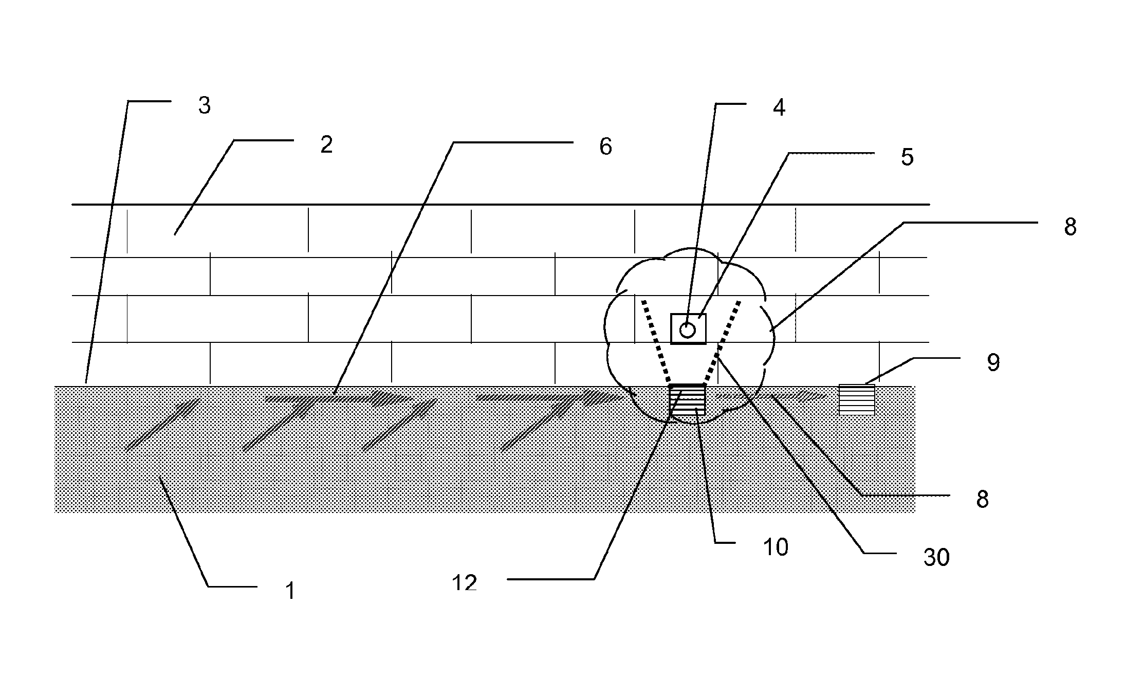
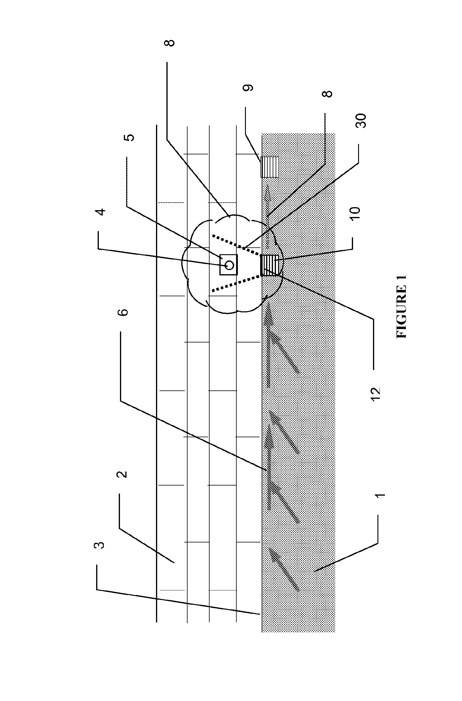
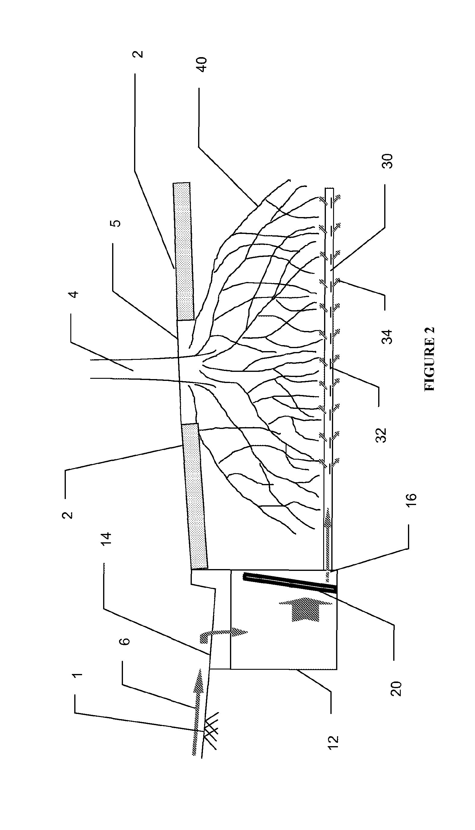
[0050]An irrigation system 10 according to a first embodiment is shown in FIGS. 1 and 2.

[0051]The system 10 comprises a receptacle, in the form of a pit 12, a distribution means, in the form of a perforated pipe 30, and a filter, in the form of a filter assembly 20.

[0052]In a typical streets cape, a road 1 and a pavement 2 are separated by a gutter 3 and rain falling on the road 1 and pavement 2 drains into the gutter 3 and travels to a storm water drain 9 where it is transported to urban streams.

[0053]It is also often the case that plants, such as a tree 4, are incorporated into the streetscape for aesthetic reasons. The pavement 2 placed around the tree 4 results in a very small area of exposed earth 5 which typically collects water for supply to the tree. However, the supply of water from rainfall is very small. As a general rule, the root structure of a tree is generally as broad as the foliage 8. Accordingly, the exposed earth 5 is insufficient to supply water to the entire roo...


PUM


Abstract

This invention relates to a system for diverting water to improve ground water supplies. The system involves collecting stormwater from hard surfaces, such as roads and pavements, and diverts the stormwater to the landscape underground, including below the road and pavement, where the water may be used for passive irrigation. More specifically, the invention relates to a water diversion system for utilizing stormwater runoff to passively irrigate plants. The system comprises a receptacle for receiving and containing a volume of stormwater runoff, and having an outlet for enabling contained stormwater to flow out of the receptacle. The system further comprises distribution means connected to the outlet of the receptacle for communicating stormwater from the receptacle to a soil profile below the level of the pavement for access by a plant, thereby irrigating the plant. The system also comprises a filter for removing solid particulates from the stormwater entering the distribution means.

Description

CROSS-REFERENCE TO RELATED APPLICATIONS[0001]This application is a U.S. National Phase filing under 35 U.S.C. §371 of International Application No. PCT / AU2010 / 001330, filed Oct. 11, 2010, and published as WO 2011 / 041850-A1 on Apr. 14, 2011, which claims benefit of priority from Australian Patent Application No. AU 2009904910, filed Oct. 11, 2009. The entire contents of each of the prior applications are incorporated herein by reference in their entirety.FIELD OF THE INVENTION[0002]The present invention relates to a water diversion system for use in urban environments. The invention has particular, although not exclusive, application to irrigation of road-side plants and trees.BACKGROUND[0003]It is increasingly becoming apparent that unmitigated stormwater runoff from urban areas is linked to degradation of the stormwater receiving waterways. Specifically, the hard surfaces, such as roads, that are impervious to rainfall prevent infiltration of rainfall and instead very efficiently t...

Claims


Application Information

Patent Timeline
Patent Type & Authority Patents(United States)
IPC IPC(8): A01G29/00
CPCA01G25/06E03F1/002Y10T137/794
Inventor WIESE, RODNEY, NEVILLE
Owner WIESE INNOVATIONS
Learn More