
Pickup system for stringed musical instruments comprises of non-humbucking pickups with noise cancelling by current injection

a pickup system and pickup technology, applied in the field of noise cancellation system for electric stringed instruments, can solve the problems of changing the sound produced by signal, instrument will stop functioning, and not being a true ground, and achieve the effect of eliminating nois

Active Publication Date: 2014-04-22
LIU YUNGMAN ALAN
View PDF6 Cites 9 Cited by
  • Summary
  • Abstract
  • Description
  • Claims
  • Application Information

AI Technical Summary

Benefits of technology

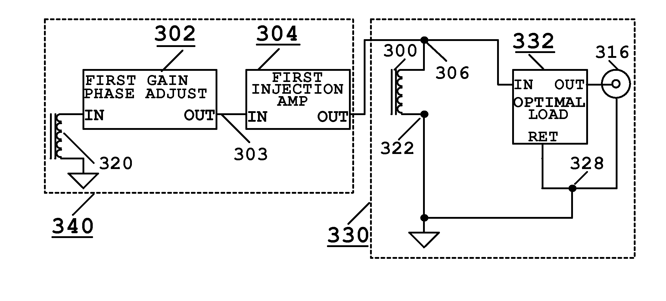
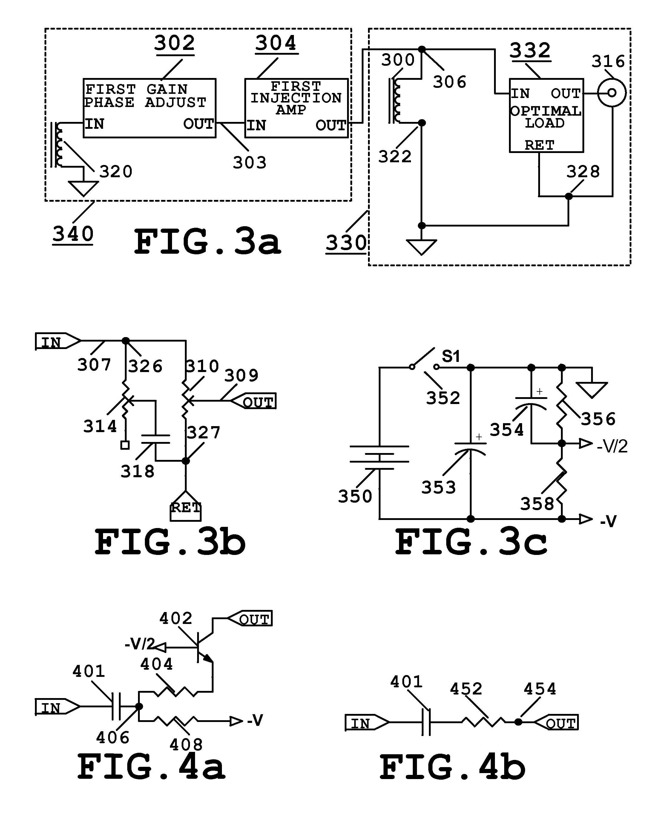
The invention is a pickup system for stringed instruments that improves the sound quality by cancelling out unwanted electromagnetic noise. It uses a single or multiple pickup coils called Signal Coils, a noise sensing means, and a special injection amp with high output impedance. The output of the noise sensing means is transformed into a current signal and directly injected into the Signal Coil. The resulting current signal cancelled out the noise. This system allows for a simplified design and can be easily retrofitted into existing stringed instruments without modifying the pickup circuits. The noise cancellation enables better sound quality and avoids the need for active circuitry in the pickup circuit. Furthermore, the instrument can still function without power, making it more versatile and reliable.

Problems solved by technology

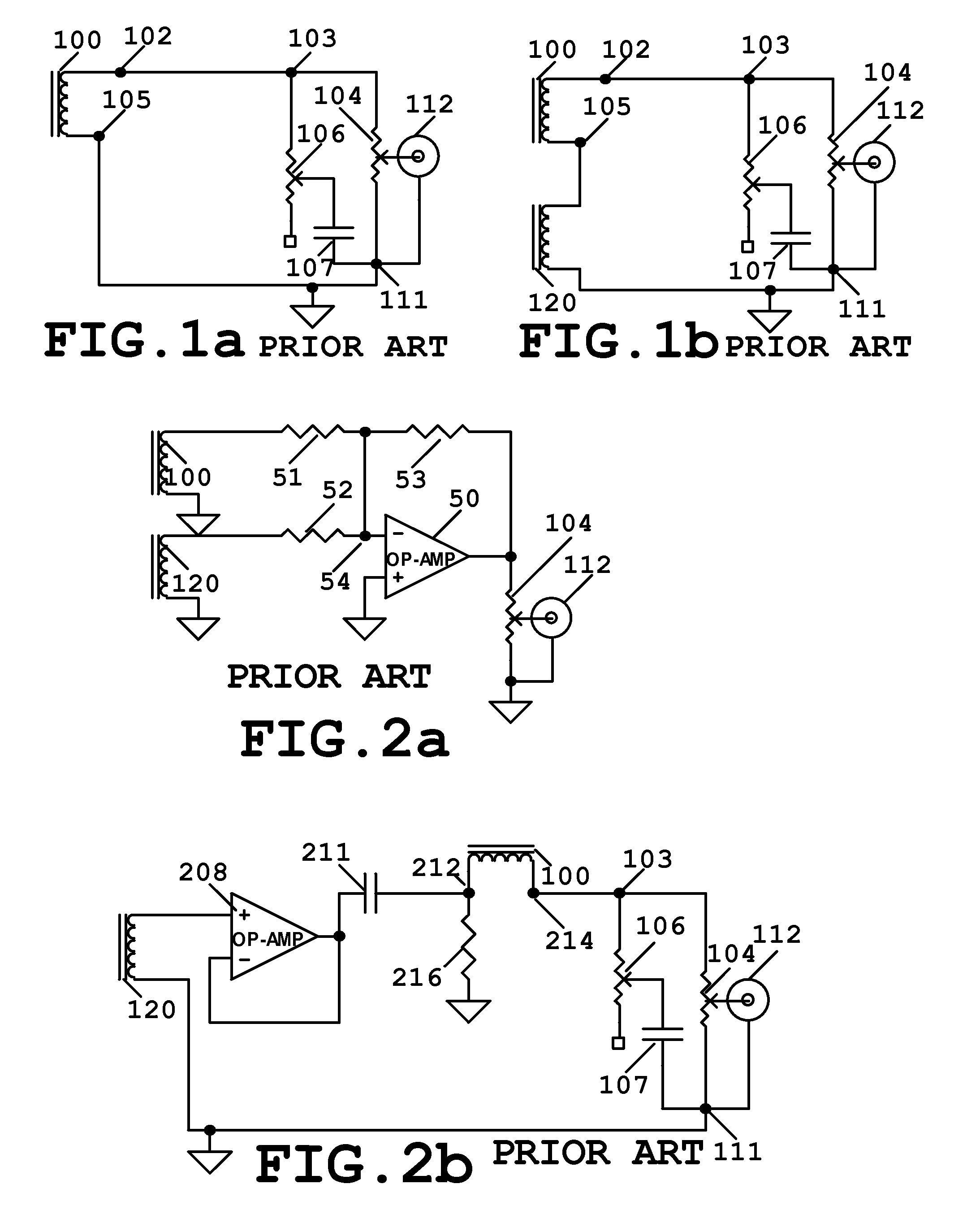
The problem in this design is, coil 120 acts as a filter, which changes the sound produced by Signal Coil 100.
Also the instrument will stop functioning if the battery runs out.
This is a problem if this happens during the performance.2) Another design using active electronics is U.S. Pat. No. 5,569,872 by Dudley Gimpel.
Although the isolation amplifier 208 has low output impedance, still, this is not a true ground.
Noise Voltage that causes humming and buzzing noise when connect to an amplifier.
It is limited by the voltage of the power source used for this embodiment, and the complexity of the Injection Amp 304.

Method used


Image

  • Pickup system for stringed musical instruments comprises of non-humbucking pickups with noise cancelling by current injection
  • Pickup system for stringed musical instruments comprises of non-humbucking pickups with noise cancelling by current injection
  • Pickup system for stringed musical instruments comprises of non-humbucking pickups with noise cancelling by current injection

Examples


Embodiment Construction

[0051]The functional blocks used in this Embodiment are described first. Operational amplifier and transistor used are but not limited to MC33179 and MPSA18 respectively.

Function Blocks Used in this Embodiment:

[0052]1) Sound Control circuit, also called Optimal Load 332 shown in FIG. 3b, The Optimal Load is used for controlling the sound and for loading the Signal Coil. It is the same as described in FIG. 1a. Other implementations of Optimal Load that can present the optimal impedance loading the Signal Coil can also be used. Optimal Load 332 in FIG. 3b comprises of a pot 310 in parallel with a tone circuit between junction 326 and 327. Tone circuit comprises of pot 314 and capacitor 318. See description in the Background section before.[0053]2) Gain Phase Adjust functional blocks 302, 302A and 302B are either comprises of amplifiers or amplifiers with simple low pass and high pass filters. The filters are used to adjust the amplitude and phase of the Cancellation Voltages from the ...


PUM


Abstract

This embodiment is a noise cancellation system for electric stringed instrument comprises of passive pickup circuit with non humbucking pickup coils called a signal coil. Each signal coil senses the unwanted electromagnetic radiation from the surrounding and produce a noise voltage that gives humming and buzzing noise through an amplifier. This embodiment cancels the noise by injecting a current signal directly into the signal coil. The impedance of the signal coil in parallel with the impedance already loading the signal coil, transform the current signal back to a voltage equal and opposite to the noise voltage; thereby, canceling each other and eliminates the noise.

Description

FIELD OF INVENTION[0001]This Embodiment is a noise cancellation system for electric stringed instruments comprises a pickup circuit with pickup coils.BACKGROUND OF INVENTION[0002]FIG. 1a is a simplified passive pickup circuit found in most of the electric stringed musical instruments. The pickup circuit is called a Strings Sensing Means in this embodiment, it comprises of a non-humbucking pickup coil named Signal Coil. Most electric stringed instruments comprise of a passive Strings Sensing Means with a single of plurality of Signal Coils. But the basic theory is similar to the circuit shown in FIG. 1a. In FIG. 1a, Coil 100 senses the vibrating strings and the unwanted electromagnetic radiation from the surrounding; thereby, producing a Signal Voltage and a Noise Voltage. The Noise Voltage produces humming or buzzing sound when connected to an amplifier. Sound characteristics produced by coil 100 is affected by the impedance loading coil 100. FIG. 1a comprises a Sound Control circui...

Claims


Application Information

Patent Timeline
IPC IPC(8): G10H3/18
CPCG10H3/18G10H3/22
Inventor LIU, YUNGMAN, ALAN
Owner LIU YUNGMAN ALAN
Learn More