Blade fixing design for protecting against low speed rotation induced wear

a technology of low speed rotation and fixing design, which is applied in the direction of propellers, propulsive elements, water-acting propulsive elements, etc., can solve the problems of blade chafing against the disk, and wear of the contact surface, etc., and achieves high stress

Active Publication Date: 2014-04-29
PRATT & WHITNEY CANADA CORP
View PDF25 Cites 4 Cited by
  • Summary
  • Abstract
  • Description
  • Claims
  • Application Information

AI Technical Summary

Benefits of technology

[0006]In one aspect, there is provided a fan rotor assembly of a gas turbine engine, comprising a disk mounted for rotation about a centerline of the engine, an array of circumferentially distributed dovetail slots defined in an outer periphery of the disk, a corresponding array of fan blades attachable to the disk, each fan blade having a blade dovetail engageable in a corresponding one of the dovetail slots, the blade dovetail having high stress regions and low stress regions, the low stress regions having a sacrificial bumper which will wear in preference to the high stress regions of the blade dovetail, the sacrificial bumper providing for a closer tolerance fit in the dovetail slots than the high stress regions, thereby shielding the high stress regions from rubbing against the disk when the rotational speed of the turbofan assembly is too low to centrifugally lock the fan blades in position on the disk.
[0007]In a second aspect, there is provided a gas turbine engine rotor assembly comprising a rotor disk mounted for rotation about an axis and having a plurality of blade mounting slots circumferentially distributed about a periphery of the rotor disk for receiving complementary blade fixing portions of a set of blades, wherein each blade fixing portion has low stress regions and high stress regions, and wherein bumper surfaces are provided in the low stress regions away from the high stress regions so that when the rotational speed of the rotor assembly is too low to centrifugally lock the blades in position on the disk, the bumper surfaces contact the disk and shield the high stress regions from contacting the disk, thereby protecting the high stress regions of the blade fixing portions from low speed rotation induced wear.

Problems solved by technology

However, when the fan rotates at low speeds, such as during windmilling, the centrifugal force is not sufficient to prevent the blade dovetails from moving in the dovetail slots.
The opposing gravitational forces on the blade during such low speed rotation cause the blade to chafe against the disk due to the play at the joint between the disk and the blades.
This low load high cycle event causes wear of the contacting surfaces.
Such low speed rotation or windmilling induced wear can result in wear in critical stress locations and, thus, lead to premature retirement of blades and disk from service.
Theses inserts are extra parts requiring extra time to make and install.
They contribute to the overall complexity of the engine.

Method used


Image

  • Blade fixing design for protecting against low speed rotation induced wear
  • Blade fixing design for protecting against low speed rotation induced wear
  • Blade fixing design for protecting against low speed rotation induced wear

Examples


Embodiment Construction

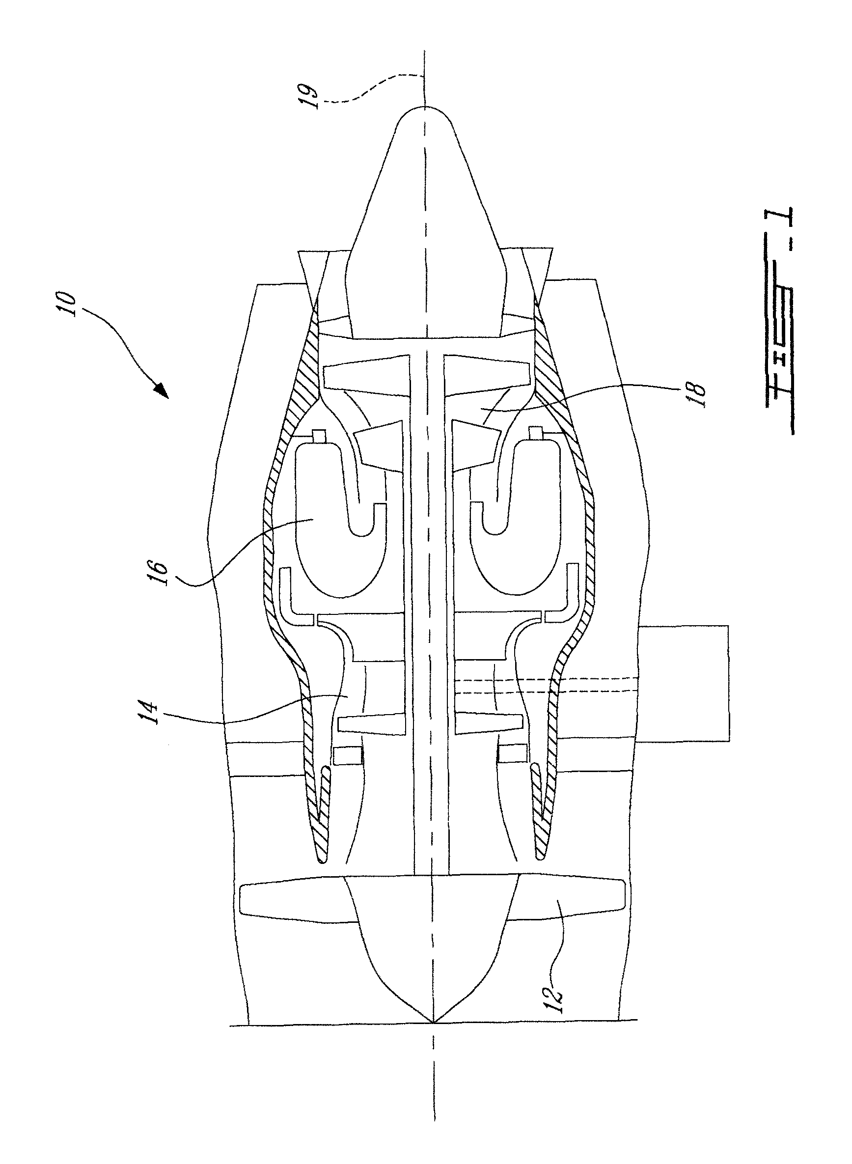
[0012]FIG. 1 illustrates a gas turbine engine 10 of a type preferably provided for use in subsonic flight, generally comprising in serial flow communication a fan 12 through which ambient air is propelled, a multistage compressor 14 for pressurizing the air, a combustor 16 in which the compressed air is mixed with fuel and ignited for generating an annular stream of hot combustion gases, and a turbine section 18 for extracting energy from the combustion gases.

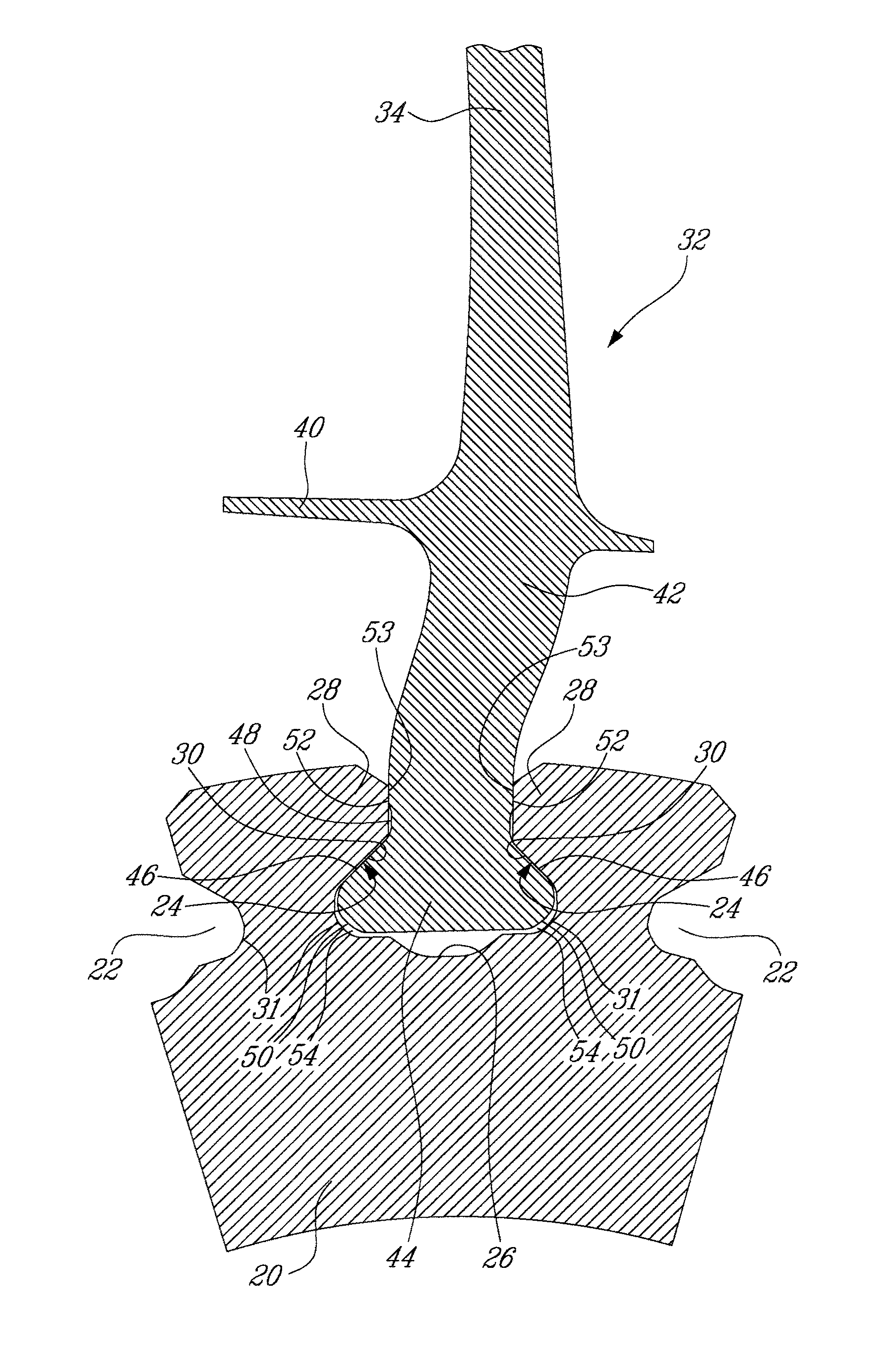
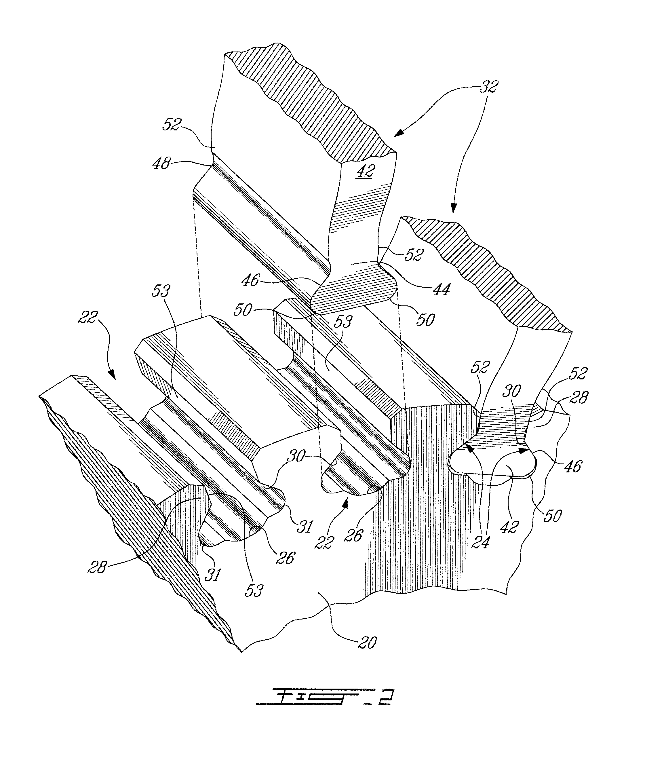
[0013]The fan 12 includes a disk 20 (FIGS. 2 and 3) mounted for rotation about the engine centerline 19. A plurality of circumferentially spaced-apart blade mounting slots 22 are defined in the outer periphery of the disk 20. The slots 22 may be provided in the form of dovetail slots. Each slot 22 is axially bounded by a pair of opposed sidewalls 24 extending longitudinally in the axial direction from a front side to a rear side of the disk 20. The term “axial” is herein intended to refer not only to directions strictly paralle...


PUM


Abstract

The blade dovetails and associated dovetail slots of a gas turbine engine rotor assembly are shaped so that during windmilling the high stress regions of the blade dovetails are shielded from rubbing against the disk and vice versa. Bumper surfaces are provided in low stress regions of the dovetail assembly such that the windmilling contact points between the blade dovetails and the disk are in non-critical areas of the dovetail assembly.

Description

TECHNICAL FIELD[0001]The application relates generally to gas turbine engines and, more particularly, to a new blade / disk fixing design for protecting predetermined regions of a blade root and / or disk from low speed rotation induced wear.BACKGROUND OF THE ART[0002]Turbofan blades are typically provided with blade dovetail which are loosely mounted in complementary-shaped dovetail slots defined in the outer periphery of the rotor hub of the fan rotor. At engine operating speeds, the blades are urged firmly in position by the centrifugal force, thereby locking the blade dovetails against movement in the associated dovetail slots. However, when the fan rotates at low speeds, such as during windmilling, the centrifugal force is not sufficient to prevent the blade dovetails from moving in the dovetail slots. Windmilling may occur when wind blows through the engine of a parked aircraft causing the fan rotor to slowly rotate. Windmilling can also occur when an aircraft crew shutdown a malf...

Claims


Application Information

Patent Timeline
Patent Type & Authority Patents(United States)
IPC IPC(8): F01D5/30
CPCF05D2260/30F01D5/3007
Inventor BARNETT, BARRYBONNIERE, PHILIPPE
Owner PRATT & WHITNEY CANADA CORP
Why Eureka
Try Eureka