Electrical connector with grounding contact having forked soldering branches

a grounding contact and electrical connector technology, applied in the direction of connection contact member material, securing/insulating coupling contact member, coupling device connection, etc., can solve the problems of manual work, cable warpage, and high labor intensity of the soldering section, so as to improve product efficiency and reduce labor intensity

Inactive Publication Date: 2014-04-29
LUXSHARE PRECISION IND SHENZHEN
View PDF13 Cites 42 Cited by
  • Summary
  • Abstract
  • Description
  • Claims
  • Application Information

AI Technical Summary

Benefits of technology

[0008]The present invention provides a cable connector compatible to type-A USB 3.0 standard. The cable connector includes an insulative housing, a plurality of contacts retained in the insulative housing and a metallic shell enclosing the insulative housing. The insulative housing includes a tongue plate which defines a mating portion enclosed by the metallic shell. The plurality of contacts are divided into a first contact group and a second contact group. The first contact group includes a plurality of first contacts each of which comprises a flat first contacting section extending onto the mating portion, a first retaining section fixed in the insulative housing and a first soldering section for being connected to a cable. The second contact group includes a plurality of second contacts each of which comprises a resilient second contacting section protruding upwardly beyond the first contacting sections, a second retaining section fixed in the insulative housing and a second soldering section for being connected to a cable. The second contacts includes a first pair of high-speed differential signal contacts, a second pair of high-speed differential signal contacts and a grounding contact disposed between the first pair and the second pair of high-speed differential signal contacts. The second soldering section of the grounding contact is of a forked manner and includes at least a first branch and a second branch. As a result, it is more effective to solder the second soldering section of the grounding contact with a cable without any manual alignment work.

Problems solved by technology

However, since the space of the insulative housing is very limited, if soldering sections of the nine contacts are of the same configuration, such soldering sections are very intensive.
Such manual work might warp the cables and is harmful to improve product efficiency and reduce cost.

Method used


Image

  • Electrical connector with grounding contact having forked soldering branches
  • Electrical connector with grounding contact having forked soldering branches
  • Electrical connector with grounding contact having forked soldering branches

Examples


Embodiment Construction

[0017]Reference will now be made to the drawing figures to describe the embodiments of the present invention in detail. In the following description, the same drawing reference numerals are used for the same elements in different drawings.

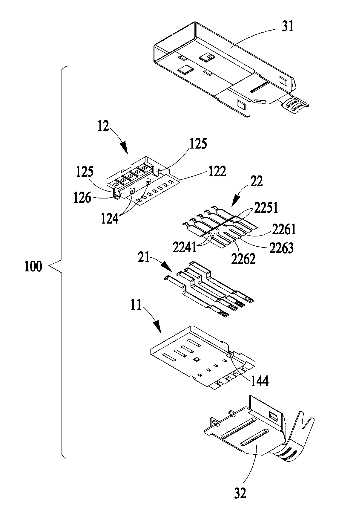
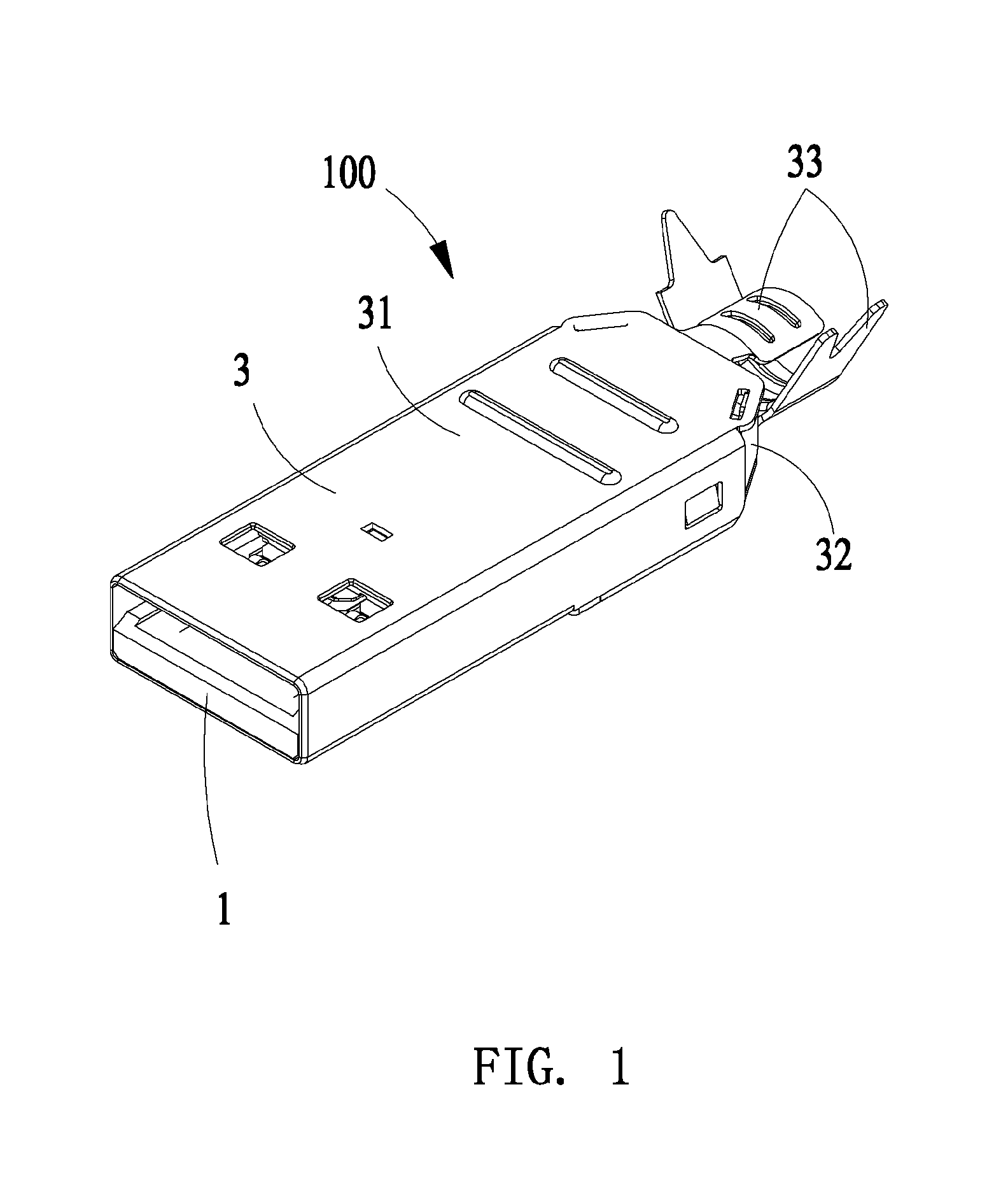
[0018]Referring to FIGS. 1 to 5, the present invention discloses an electrical connector compatible to type-A USB 3.0 standard. According to the illustrated embodiment of the present invention, the electrical connector is a cable connector 100 and includes an insulative housing 1, a plurality of contacts 2 retained in the insulative housing 1 and a metallic shell 3 fixed to and enclosing the insulative housing 1.

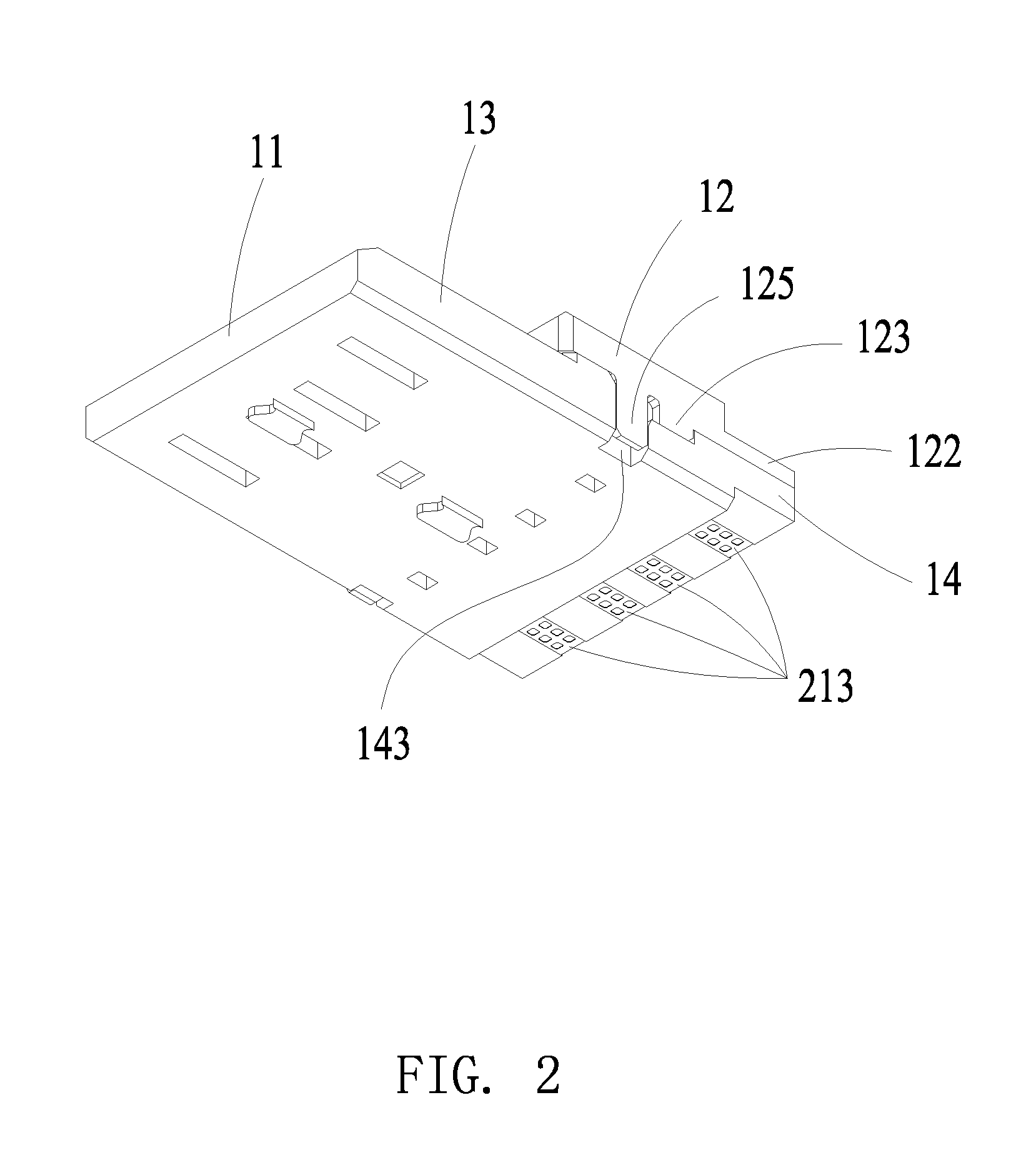
[0019]Referring to FIGS. 2 to 5, the insulative housing 1 includes a tongue plate 11 and an insulative block 12 attached to the tongue plate 11. The tongue plate 11 comprises a front mating portion 13 for mating with a mateable receptacle connector (not shown) and a rear base portion 14 extending backwardly from the mating portion 13. The m...


PUM


Abstract

A cable connector compatible to type-A USB 3.0 standard includes a number of contacts divided into a first contact group and a second contact group. The first contact group is compatible to USB 2.0 standard. The second contact group includes a number of second contacts having a first pair of high-speed differential signal contacts, a second pair of high-speed differential signal contacts and a grounding contact disposed between the first pair and the second pair of high-speed differential signal contacts. The second soldering section of the grounding contact is of a forked manner and includes at least a first branch and a second branch. As a result, it is more effective to solder the second soldering section of the grounding contact with a cable without any manual alignment work.

Description

BACKGROUND OF THE INVENTION[0001]1. Field of the Invention[0002]The present invention relates to an electrical connector, and more particularly, to a cable connector with a grounding contact which has forked soldering branches for improving soldering efficiency of the cable connector in mass production.[0003]2. Description of Related Art[0004]On November 2008, a new generation of USB 3.0 (super high-speed USB) enacted by industry-leading corporations including Intel, Microsoft, HP, TI, NEC and ST-NXP etc. was released. The USB 3.0 standard provides transmission speed 10 times quicker than the USB 2.0 standard and has higher energy efficiency so that the USB 3.0 standard can be applied in PC peripheral devices and consumer electronics.[0005]The development of the USB (Universal Serial Bus) standards is as follows: the first version, known as USB 1.0, was released on 1996 and its transmission speed is only up to 1.5 Mb / s; two years later, the USB 1.0 was upgraded to USB 1.1 with its t...

Claims


Application Information

Patent Timeline
Patent Type & Authority Patents(United States)
IPC IPC(8): H01R13/648
CPCH01R4/027H01R9/034H01R13/65914
Inventor LI, BINCHENG, WEI-YA
Owner LUXSHARE PRECISION IND SHENZHEN
Why Eureka
Try Eureka