
Control device of hybrid vehicle

a control device and hybrid technology, applied in the direction of electric control, ignition automatic control, instruments, etc., can solve the problems of increasing the frequency of occurrence of rattling noise, increasing the time until rattling noise, and increasing the rotation speed of the engine, so as to suppress the rattling noise, and reduce the rattling noise

Active Publication Date: 2014-04-29
TOYOTA JIDOSHA KK
View PDF23 Cites 4 Cited by
  • Summary
  • Abstract
  • Description
  • Claims
  • Application Information

AI Technical Summary

Benefits of technology

The patent text describes a method for reducing rattling noise in an electric vehicle by controlling the output torque of the electric motor for running. This method includes various controls such as suppressing the exhaust gas recirculation amount, shifting the air-fuel ratio, delaying the ignition timing, and controlling the remaining amount of combustion gas in the cylinder in the exhaust stroke. By implementing these controls, rattling noise can be reduced without changing the engine rotation speed, resulting in improved fuel efficiency and a more comfortable driving experience for the user. The method also includes a predetermined range for the output torque of the electric motor for running to optimize fuel consumption and reduce gear bearing noise. Overall, this patent provides a technical solution for reducing rattling noise in electric vehicles.

Problems solved by technology

On the other hand, this may increase a frequency of occurrence of the rattling noise or may increase the time until the rattling noise is reduced.
However, when the transition time is made shorter, or when the engine optimum fuel consumption line and the rattling noise avoidance operation line are more distant from each other, the engine rotation speed more rapidly increases and, therefore, a user may easily feel uncomfortable.
In other words, the user may feel uncomfortable about a rapid increase in the engine rotation speed.
The problem as described above is not known and no proposal has been made on reducing the rattling noise without giving an uncomfortable feeling to a user about a change in the engine rotation speed.

Method used


Image

  • Control device of hybrid vehicle
  • Control device of hybrid vehicle
  • Control device of hybrid vehicle

Examples


first embodiment

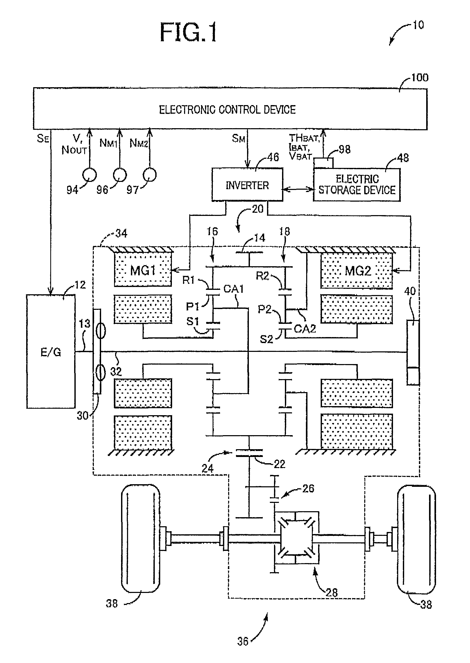
[0031]FIG. 1 is a diagram for explaining a general configuration of a hybrid vehicle 10 (hereinafter referred to as a vehicle 10) to which the present invention is applied, and is a block diagram for explaining a main portion of a control system disposed for controlling the portions of the vehicle 10. In FIG. 1, the vehicle 10 includes a transmission portion 20 having a power distribution mechanism 16 distributing power output from an engine 12 acting as a drive power source for running to a first electric motor MG1 and an output gear 14, a gear mechanism 18 coupled to the output gear 14, and a second electric motor MG2 coupled via the gear mechanism 18 to the output gear 14 in a power transmittable manner. The transmission portion 20 is preferably used in, for example, an FF (front-engine front drive) type vehicle in which the transmission portion 20 is transversely placed in the vehicle 10, and makes up a power transmission device 36 along with a counter gear pair 24 made up of th...

second embodiment

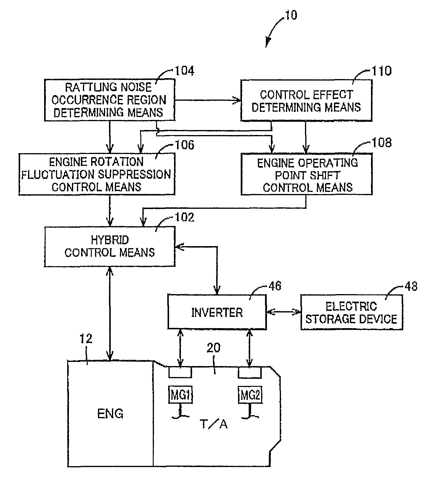
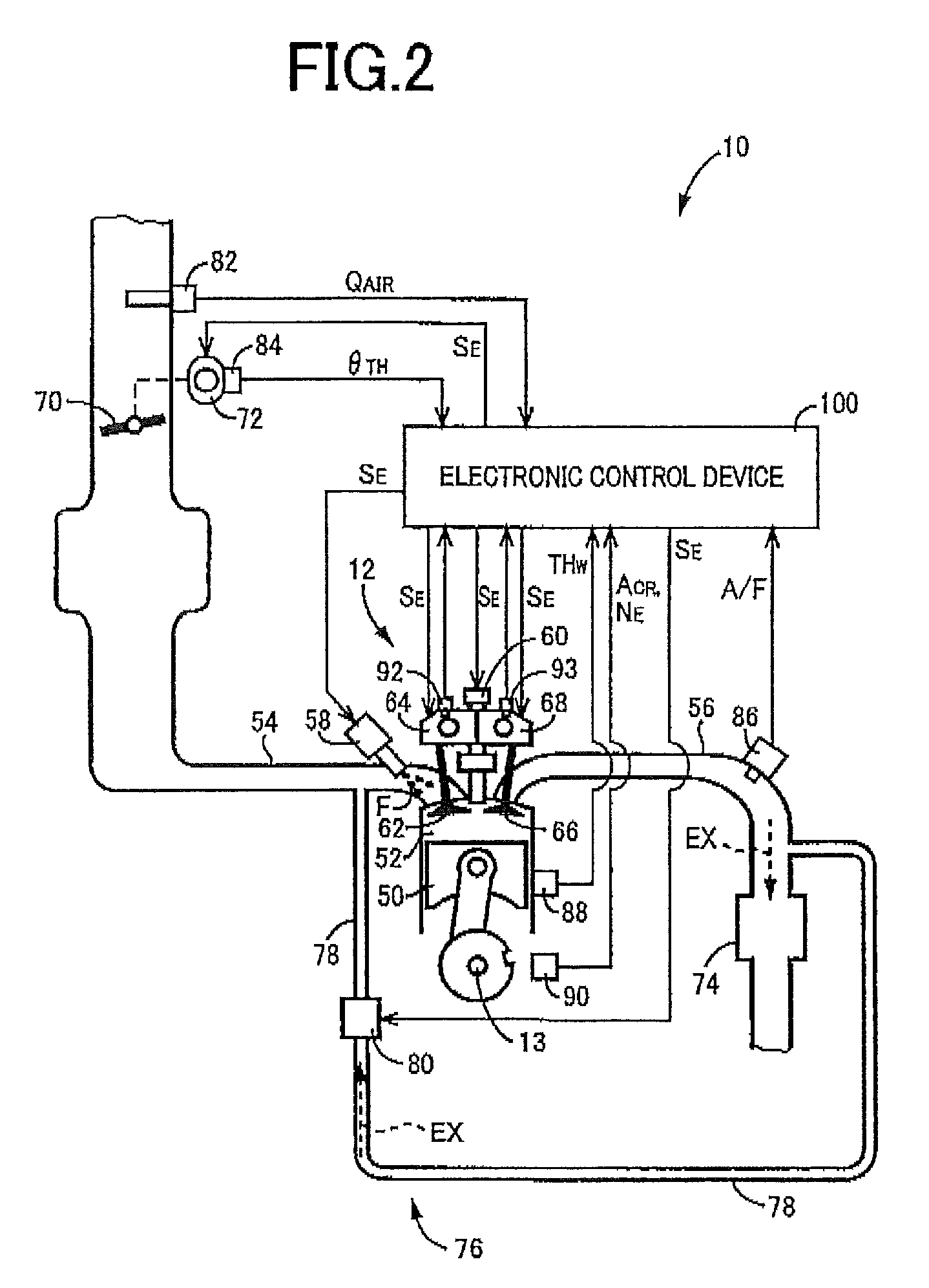
[0071]In the embodiment, if the second electric motor torque TM2 is within the rattling noise occurrence region G, the engine rotation fluctuation suppression control is provided to suppress the engine rotation fluctuations without changing the engine operating point from the engine optimum fuel consumption line. Apart from this engine rotation fluctuation suppression control, the engine operating point shift control is also described in detail that shifts the engine operating point from the engine optimum fuel consumption line onto the rattling noise avoidance operation line to actively increase the engine rotation speed NE for reduction or avoidance of the rattling noise. Comparing the engine rotation fluctuation suppression control with the engine operating point shift control in terms of fuel consumption, the engine rotation fluctuation suppression control not changing the engine operating point from the engine optimum fuel consumption line seems advantageous.

[0072]In the EGR am...

third embodiment

[0081]In the embodiments, each of the engine rotation fluctuation suppression control and the engine operating point shift control is solely provided. Even when rattling noise can be reduced, the engine rotation fluctuation suppression control may not be able to avoid the rattling noise alone. As described above, the engine operating point shift control may give an uncomfortable feeling to a user due to an increase in the engine rotation speed NE. In this regard, it is found out that if the rattling noise is reduced to some extent by the engine rotation fluctuation suppression control, the rattling noise avoidance operation line can be set with an increase in the engine rotation speed NE suppressed to some extent in the engine operating point shift control. Therefore, in this embodiment, if the second electric motor torque TM2 is within the rattling noise occurrence region G, the engine rotation fluctuation suppression control and the engine operating point shift control are provide...


PUM


Abstract

Providing a control device of a hybrid vehicle capable of reducing a rattling noise without changing an engine rotation speed.If the second electric motor torque TM2 is within the rattling noise occurrence region G, the engine rotation fluctuation suppression control (at least one of the EGR amount suppression control, the self-EGR amount suppression control, the lean-burn control, and the ignition delay control) is provided to suppress the engine rotation fluctuations as compared to during normal running while the second electric motor torque TM2 is out of the rattling noise occurrence region G and, therefore, the engine rotation fluctuations can be suppressed to reduce the a rattling noise without changing an engine rotation speed NE. Thus, the rattling noise can be reduced without giving an uncomfortable feeling to a user due to a change in the engine rotation speed NE.

Description

TECHNICAL FIELD[0001]The present invention relates to a control device of a hybrid vehicle including a power distribution type electric differential portion and particularly to a technique of reducing gear bearing noise in the electric differential portion due to rotation fluctuations of an engine.BACKGROUND ART[0002]A hybrid vehicle is well known that includes an electric differential portion having a differential mechanism distributing power from an engine to a differential electric motor and an output rotating member and an electric motor for running coupled in a power transmittable manner (i.e., coupled directly or indirectly via a gear mechanism) to the output rotating member such that a differential state of the differential mechanism is controlled by controlling an operating state of the differential electric motor. For example, this corresponds to a hybrid vehicle described in Patent Document 1.[0003]In the hybrid vehicle as described above, for example, gear bearing noise m...

Claims


Application Information

Patent Timeline
Patent Type & Authority Patents(United States)
IPC IPC(8): G06F7/00
CPCB60W20/00B60K6/445B60W10/06B60W30/20B60W2710/0661F02D41/1475F02D41/1498F02P5/1502Y02T10/6239Y10S903/903F02D13/0219F02D37/02F02D41/006F02D41/1497F02D2041/001F02D2250/18F02P5/045F02D19/06Y02T10/30Y02T10/40Y02T10/62B60W20/15
Inventor HARADA, TAKUITO, MASATOSHISHIIBA, KAZUYUKIKANAYAMA, TAKESHI
Owner TOYOTA JIDOSHA KK
Learn More