
Transmission line with left-hand characteristics including an interdigital capacitor with partially overlapping fingers

a technology of interdigital capacitor and left-hand finger, which is applied in the direction of capacitors, waveguides, resonators, etc., can solve the problems of difficult fabrication and processing of interdigital capacitors, the restriction of the performance improvement of transmission lines, and the inability to manufacture interdigital capacitors b>100/b>, etc., to achieve the effect of increasing the capacitance and being easy to fabrica

Inactive Publication Date: 2014-05-06
EMW CO LTD
View PDF33 Cites 0 Cited by
  • Summary
  • Abstract
  • Description
  • Claims
  • Application Information

AI Technical Summary

Benefits of technology

The present invention aims to solve issues in prior art design by providing an interdigital capacitor that can increase capacitance while maintaining design flexibility and ease of fabrication. Additionally, a compact inductor without a cut-off frequency can be obtained, and a broad transmission band LH transmission line and coupler can be realized. The technical effects of the invention revolve around achieving greater capacitance, smaller size, and improved transmission band capabilities.

Problems solved by technology

The structural limitation of each constituent element of such a conventional LH transmission line contributes to restriction of performance improvement of the transmission line.
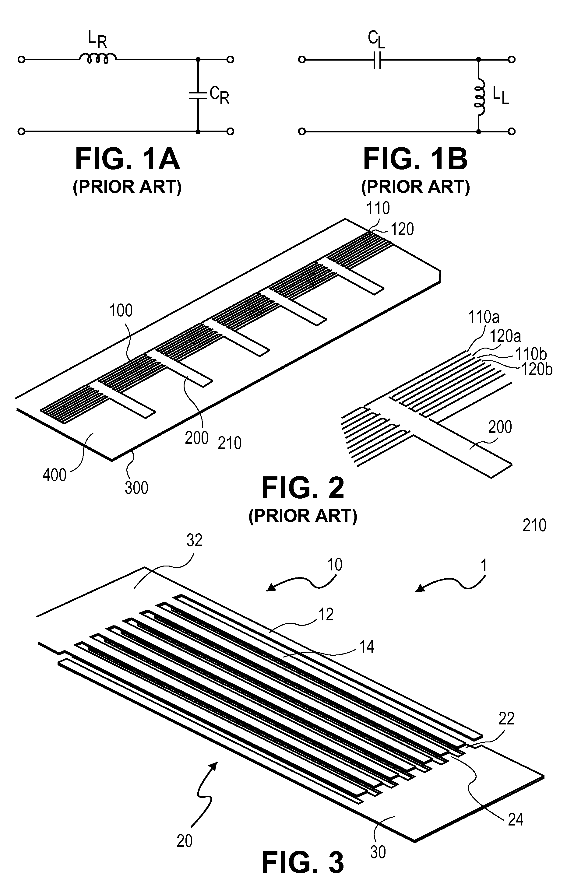
First the interdigital capacitor 100 is disadvantageous in that its capacitance is smaller than a capacitance of a multi-layered capacitor.
Besides this, since it is required that the respective fingers should be formed to accurately intersect with one another in a criss-cross fashion, the interdigital capacitor 100 is very difficult to fabricate and process.
The multi-layered capacitor has a demerit in that the adjustment of capacitance is performed only by adjusting the interval between the conductors and the area of the conductors, a degree of freedom of design is degraded, which generally makes it difficult to be used in the LH transmission line.
However, the above U.S. patents entail a problem in that since it has a similar construction as that of the multi-layered capacitor, a degree of freedom of design is decreased and its structure is complicated to thereby increase the manufacturing cost.
Due to the structural limitation of the interdigital capacitor 100 and the stub inductor 200, the conventional LH transmission line has a lot of limitations in expansion of the transmission band and miniaturization thereof.

Method used


Image

  • Transmission line with left-hand characteristics including an interdigital capacitor with partially overlapping fingers
  • Transmission line with left-hand characteristics including an interdigital capacitor with partially overlapping fingers
  • Transmission line with left-hand characteristics including an interdigital capacitor with partially overlapping fingers

Examples


Embodiment Construction

[0037]Reference will now be made in detail to a preferred embodiment of the present invention with reference to the attached drawings.

[0038]As used herein, the terms “inductor”, “capacitor” and “transmission line” are defined to exhibit a superior electrical characteristic in their devices and constituent elements. This does not means that the devices and constituent elements are operated only by the inductor, the capacitor and the transmission line.

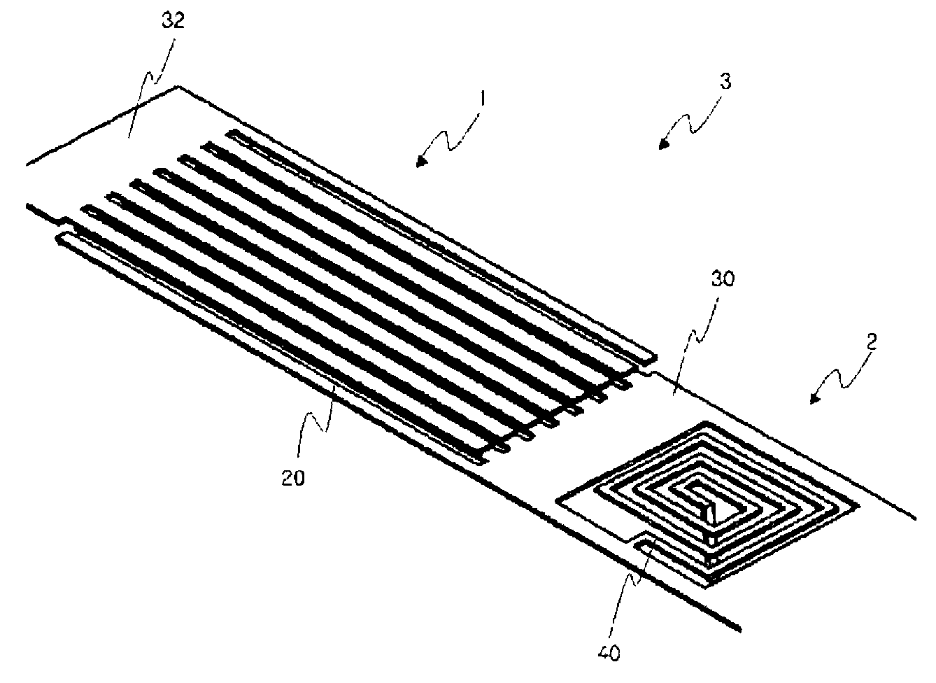
[0039]FIG. 3 is a perspective view showing an interdigital capacitor 1 according to one embodiment of the present invention.

[0040]The interdigital capacitor 1 comprises two sets of fingers 10 and 20 that are substantially disposed in parallel with each other. The two finger sets 10 and 20 include two pairs of fingers 12, 14 and 22, 24, respectively, each pair of fingers being disposed spaced apart from each other and connected at one ends thereof to each other.

[0041]Now, only some of fingers shown in the drawing will be described hereaft...


PUM


Abstract

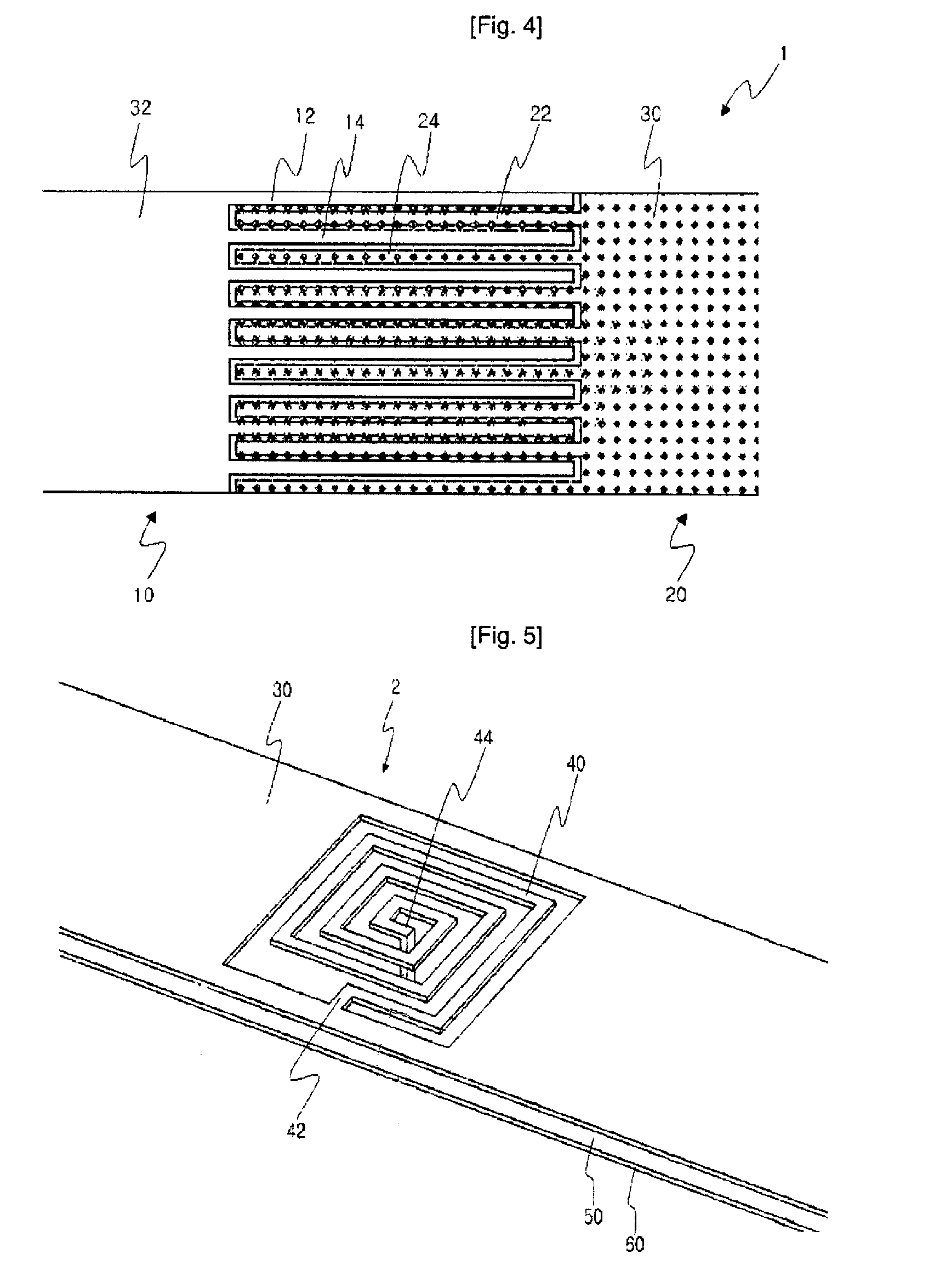
There is herein disclosed an interdigital capacitor, an inductor, and an LH transmission line and a coupler using the interdigital capacitor and the inductor. The interdigital capacitor comprises two finger sets which are substantially disposed in parallel with each other. Fingers of each finger set are overlapped at outer edges thereof with each other to thereby generate capacitance. The inductor is formed substantially spirally inside the transmission line, so that it can have a large inductance in a compact shape and can be used in a broad frequency band. The LH transmission line has a broad frequency band in a compact shape, which includes interdigital capacitors connected in series with each other and inductors connected in parallel with each other. In addition, the coupler employing the LH transmission line has an excellent couplability.

Description

CROSS-REFERENCE TO RELATED APPLICATIONS[0001]This patent application is a U.S. National Phase application under 35 U.S.C. §371 of International Application No. PCT / KR2007 / 005375, filed on Oct. 30, 2007, entitled INTERDIGITAL CAPACITOR, INDUCTOR, AND TRANSMISSION LINE AND COUPLER USING THEM, which claims priority to Korean patent application number 10-2006-0105513, filed Oct. 30, 2006.TECHNICAL FIELD[0002]The present invention relates to a transmission line and a coupler, and more particularly, to a left-Handed (LH) transmission line, a coupler using the LH transmission line, and a capacitor and an inductor for implementing the LH transmission line and the coupler.BACKGROUND ART[0003]Metamaterial refers to a material or an electromagnetic structure designed artificially to exhibit a special electromagnetic characteristic which cannot be generally found in the nature. The term Metamaterial as defined herein and in the present art, generally refers to a material or an electromagnetic s...

Claims


Application Information

Patent Timeline
Patent Type & Authority Patents(United States)
IPC IPC(8): H01P3/08
CPCH01P5/08H01P3/081H01P5/00H01P3/16H01P3/08
Inventor RYOU, BYUNG HOONSUNG, WON MOKIM, GI HO
Owner EMW CO LTD
Learn More