Traffic signal control system, design method and special equipment

a traffic signal and design method technology, applied in the direction of traffic control of road vehicles, traffic signals, controlling traffic signals, etc., can solve the problems of reducing the cycle loss time, reducing the minimum green interval, and prone to phase interval accidents. , to achieve the effect of reducing the cycle loss time, reducing the start-up loss time, and reducing the minimum green interval

Inactive Publication Date: 2014-05-06
HWYL HUBBL TECH DEV CO LTD IN BEIJING
View PDF12 Cites 1 Cited by
  • Summary
  • Abstract
  • Description
  • Claims
  • Application Information

AI Technical Summary

Benefits of technology

[0026]The equation (7) is quite different from the equation in (Wu Bing, Li Ye, Fourth Edition 2009, P. 161), where a vehicle braking time is shorter than the yellow time A in the equation (7). The equation (7) is also significantly different from the equation in (Architectural Press, 2006, P. 15), where a passing time is also shorter than the yellow time A in the equation (7). In the equation (7), “the maximum clearing time of the signal i and the minimum entry time of the signal j” further enhance the safety and security. Therefore, the minimum green interval in the equation (7) is longer and safer, and the technical problem of unsafe traffic is solved.
[0030]The equation (8) further shows that there are the following four complementary technical means to mine time resources for an intersection and reduce the cycle loss time: 1. finding a key path to minimize a sum of the interval loss time between the earlier key traffic flow and the later key traffic flow; 2. selecting a preferable channelization scheme so as to reduce the minimum green interval in the key path; 3. reducing the start-up loss time l of the traffic flow by any possible technical means; 4. reducing the total sum X of the differences between the green interval and the minimum green interval of each traffic flow as small as possible until the total sum reaches 0.
[0031]In fact, although each of the four technical means has limited effectiveness, the cycle loss time may become negative when the four technical means are effected together. There are the following advantages if a signal control system has a negative cycle loss time. The total sum of the effective green time of the traffic flow in the key path is larger than the cycle and there is additional effective releasing time. The shorter the cycle loss time, the longer the additional effective releasing time. By minimizing the ratio of the cycle loss time to the cycle in the case of the rationally allowed maximum saturation degree, the absolute value of the negative cycle loss time can reach the maximum, the system cycle can reach the minimum, the proportion of the additional effective releasing time can reach the maximum, the traffic capacity and efficiency of the intersection can reach the maximum and the delay time due to stop of the vehicle can reach the minimum.

Problems solved by technology

Since the three constraints can not be determined accurately by all the typical signal control systems, there are disadvantages in the following four technical means.
The existing control design methods are completely ineffective in the case of negative cycle loss time.
Firstly, the road channelization is performed with great arbitrariness, since conventionally there is no specific numerical value index to appraise the road channelization.
Thus the minimum green interval is set to be too small, which is neither reasonable nor safe, leading to accident-proneness in the phase interval.
No literature can assure that a phase structure scheme therein is the best.
In addition, in these classic systems, it is not able to configure a countdown display and it is difficult to reduce the start-up lost time.
However, an estimation value which is very inaccurate is commonly used instead.

Method used


Image

  • Traffic signal control system, design method and special equipment
  • Traffic signal control system, design method and special equipment
  • Traffic signal control system, design method and special equipment

Examples


first embodiment

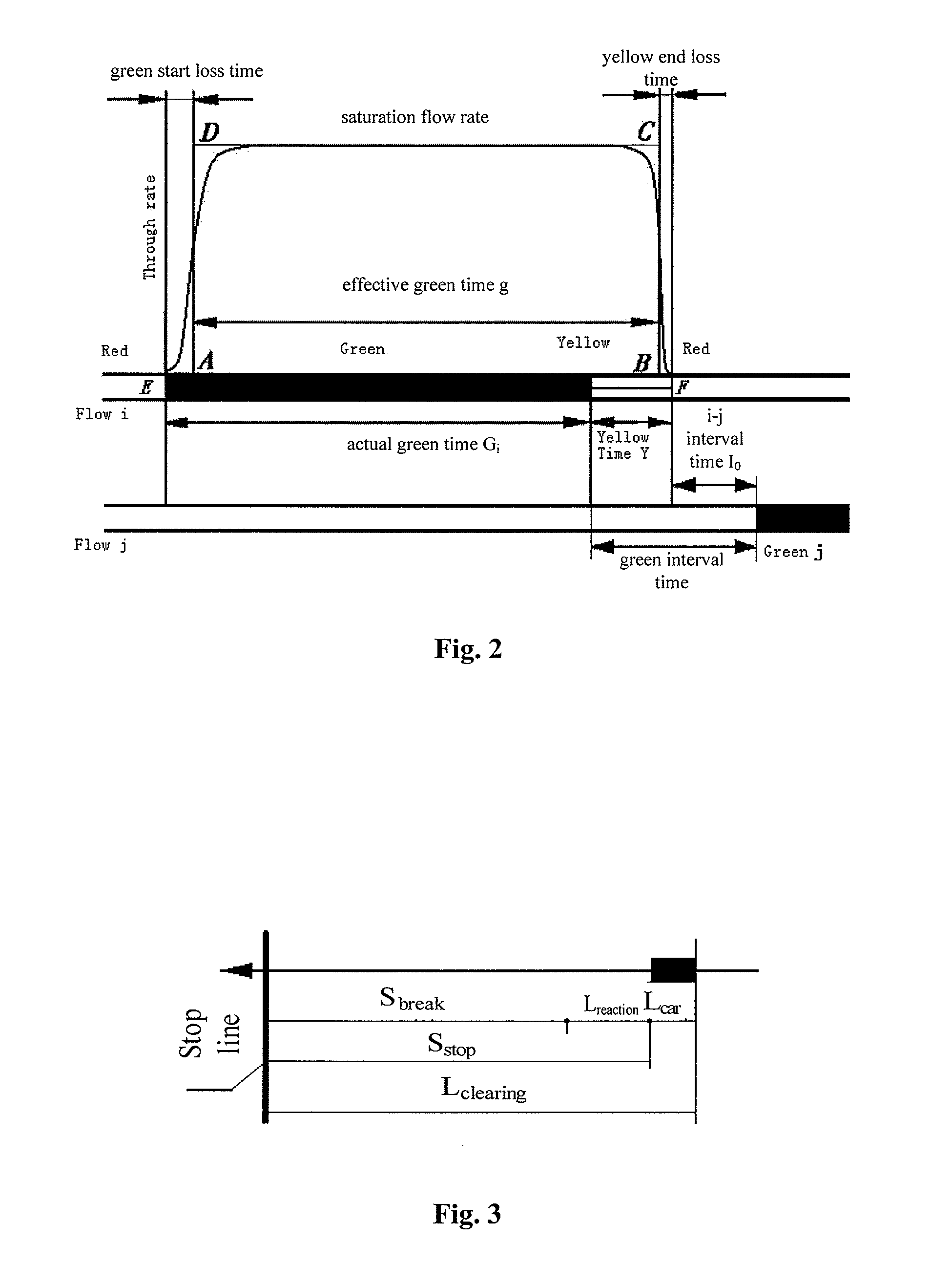
[0047]The present invention provides a traffic signal control method, including determining a control scheme by determining a minimum green interval. In a first embodiment, the information for a road channelization of an intersection may include various information in the engineering design diagram of the road channelization of the intersection. FIG. 3 illustrates relevant factors for determining a minimum yellow time A.

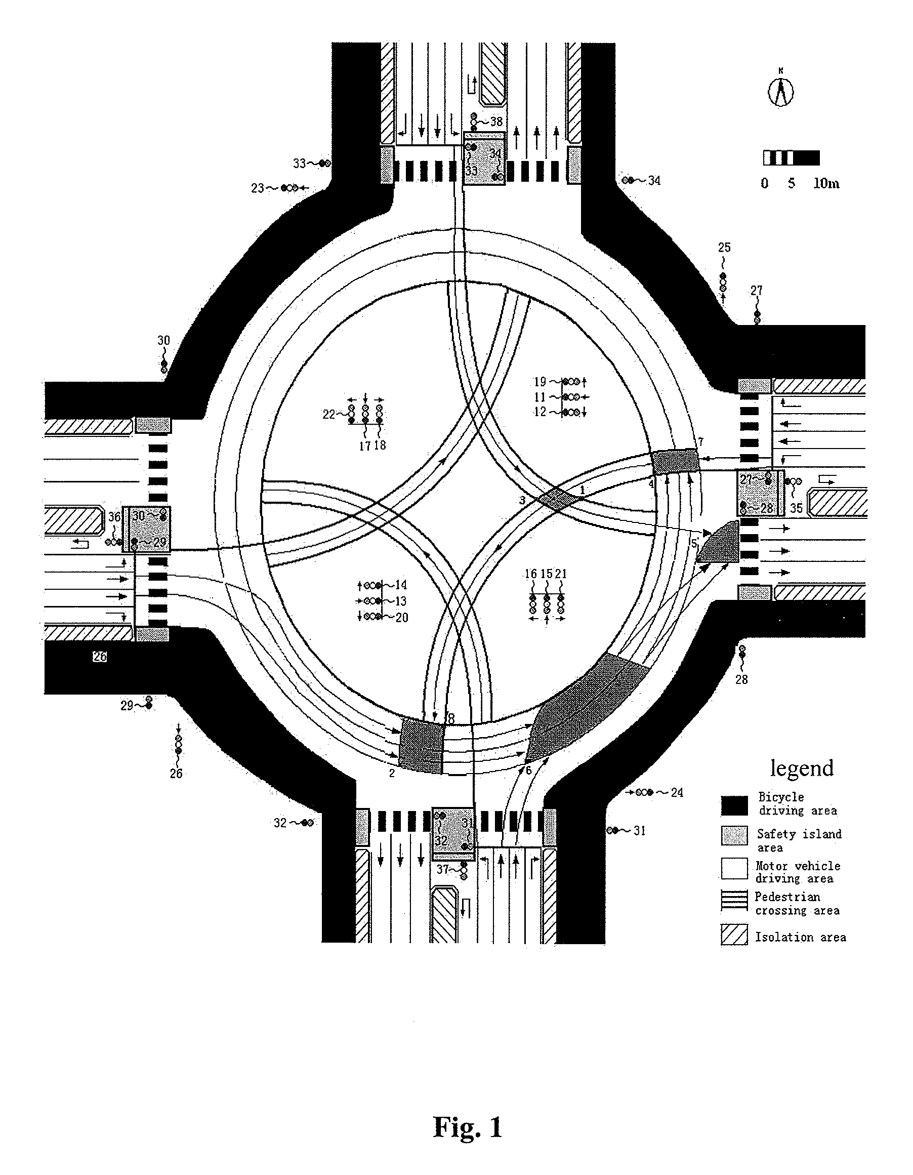
[0048]The information for road channelization shown in FIG. 1 is used. The number of each traffic lane is expressed as follows: east straight N1=2, west left N2=1, north straight N3=2, south left N4=1, west straight N5=2, east left N6=1, south straight N7=2 and north left N8=1. Position of each of critical point positions 1 to 10 is determined in the channelization scheme of FIG. 1 and a maximum clearing distance si(m) and a minimum entry distance sj(m) are measured respectively, as shown in Tables 1 and 2.

[0049]

TABLE 1the maximum clearing distance si and the minimum...

second embodiment

[0073]In a second embodiment a chain family complete classification and a chain family with the minimum average value of the cycle loss time, is in a Wang chain family. The intersection shown in FIG. 1 has totally 114 traffic flow chains which may be completely divided into 9 chain families with the traffic flow confliction and 13 chain families without the traffic flow confliction. The chain families are listed, and the cycle loss times of the traffic flow chains are calculated according to Table 3 and the results are listed in Table 4.

[0074]

TABLE 4the cycle loss times of each of chain families and the average value of the cycle losstime of the chain families according to the Wang channelization schemeserial numberbasic phase stage and the minimum green interval (second)cycle loss timeaverage(yellow time 4 s)(including each start-upvaluephase stage 1phase stage 2phase stage 3phase stage 4loss time l = 1.5 (seconds))117east and westsouth and north17released 11released 11212.5east an...

third embodiment

[0097]In a third embodiment the minimum compatible scheme of the Wang chain family for the intersection shown in FIG. 1, {Ii}: I1=1 s, I2=−2 s, I2=−1 s, I3=3 s, I4=−1 s, I4=−1 s, I5=1 s, I6=−1 s, I6=−2 s, I7=1 s, I8=−1 s, I8=−1 s, I1,3=11 s, I5,7=11 s, I7,1=12 s, I3,5=12 s, as shown in FIG. 7.

[0098]A method for determining Wang minimum green time includes the steps as following as statistical regularity indicates that there are large differences among the speed of the pedestrians due to gender, age and physical condition. Population in various speeds has the right to go across a street safely, and a simple processing using a uniform average speed should not be adopted. Population in various speeds should be defined according to the statistical regularity as follows. Population in a speed larger than a certain threshold, such as 1.5 m / s, is referred to as fast people, and population in a speed about 11.0 m / s is referred to as general people. The time spent for a pedestrian going acro...


PUM


Abstract

A traffic signal control method comprises confirming the shortest green light interval; confirming the conflict area of the different traffic flow and the key conflict point position according to the engineering design for road canalization; confirming the longest clear distance si(m) of the traffic tail unit of green light i and the shortest entry distance sj(m) of the traffic head unit of green light j in conflict with green light i; calculating the longest clear time Max{ti} of the traffic tail unit of green light i and the shortest entry time Min{tj} of the traffic head unit of green light j; calculating the shortest green light interval Iij=A+Max{ti}−Min{tj}; confirming the control scheme for the crossing according to the shortest green light interval and sending the control instruction to the traffic signal display device for displaying in real time according to the control scheme. A traffic signal control system and special equipment are also provided.

Description

CROSS REFERENCE TO RELATED APPLICATIONS[0001]This application is a 35 U.S.C. §371 national stage application of PCT / CN2011 / 070879 filed Feb. 1, 2011, which claims the benefit of Chinese Patent Application No. 201010103079.2 filed Feb. 1, 2010, each of which is hereby incorporated herein by reference in its entirety for all purposes.STATEMENT REGARDING FEDERALLY SPONSORED RESEARCH OR DEVELOPMENT[0002]Not applicable.FIELD OF THE INVENTION[0003]The present invention generally relates to the field of traffic information engineering and control, and in particular to a control system and design method for a traffic signal on an intersection and a special device.BACKGROUND OF THE INVENTION[0004]At a grade intersection, a conflict area is a space which traffic units in different flow directions have to pass. A critical point is the most dangerous point in the conflict area. The traffic units enter into the conflict area in turn according to signal sequence. the movement of a traffic tail un...

Claims


Application Information

Patent Timeline
Patent Type & Authority Patents(United States)
IPC IPC(8): G08G1/00
CPCG08G1/07
Inventor WANG, QIANWANG, DAHAIYE, NAN
Owner HWYL HUBBL TECH DEV CO LTD IN BEIJING
Why Eureka
Try Eureka