Cooling apparatus for switchgear with enhanced busbar joint cooling

a cooling apparatus and switchgear technology, applied in the field of switchgear circuit breakers, can solve the problems of overly difficult to dissipate heat losses caused by the nominal current inside the switchgear compartment, inefficient heat transfer process, and the typical thermal limitation of the switchgear product by its nominal curren

Active Publication Date: 2014-05-06
ABB (SCHWEIZ) AG
View PDF22 Cites 7 Cited by
  • Summary
  • Abstract
  • Description
  • Claims
  • Application Information

AI Technical Summary

Benefits of technology

[0005]An objective of the invention is to fulfill the need referred to above. In accordance with the principles of the present invention, this objective is achieved by providing a cooling apparatus for a switchgear having at least one primary contact constructed and arranged to connect to a terminal of a circuit breaker, with a busbar joint being connected to the primary contact. The cooling apparatus includes an evaporator constructed and arranged to be associated with the primary contact. A condenser is located at a higher elevation than the evaporator. Heat pipe structure fluidly connects the evaporator with the condenser. Heat transfer structure is coupled with the busbar joint for removing heat from the busbar joint. Working fluid is in the evaporator so as to be heated to a vapor state, with the heat pipe structure being constructed and arranged to transfer the vapor to the condenser and to passively return condensed working fluid back to the evaporator for cooling the at least one primary contact.
[0006]In accordance with another aspect of an embodiment, heat transfer structure is provided for a switchgear having one or more primary contacts constructed and arranged to connect to a terminal of a circuit breaker, and busbar joints connected to the primary contacts. Each busbar joint includes at least a pair of first busbars in a parallel arrangement defining a space there-between. The heat transfer structure includes a plurality of fins and a plurality of heat spreaders that pass through the fins to join the fins so that the fins are in spaced relation. The heat transfer structure is constructed and arranged to be received in the space between the pair of first busbars so that the heat spreaders distribute heat along the first busbars, with the fins transferring heat to surrounding air by natural convection.
[0007]In accordance with another aspect of an embodiment, a method of cooling a switchgear is provided. The switchgear has at least one primary contact constructed and arranged to connect to a terminal of a circuit breaker, and a busbar joint connected to the primary contact. The method associates an evaporator with the primary contact. A condenser is located at a higher elevation than the evaporator. A heat pipe structure fluidly connects the evaporator with the condenser, and a working fluid is provided in the evaporator. The method couples heat transfer structure to the busbar joint. Heat is transferred from the primary contact to the working fluid to cause the working fluid to evaporate in the evaporator with the evaporated vapor being delivered to the condenser via the fluid conduit structure. Heat is removed from the busbar joint via the heat transfer structure. The working fluid that condenses in the condenser is passively retuned to the evaporator via the fluid conduit structure
[0008]Other objectives, features and characteristics of the present invention, as well as the methods of operation and the functions of the related elements of the structure, the combination of parts and economics of manufacture will become more apparent upon consideration of the following detailed description and appended claims with reference to the accompanying drawings, all of which form a part of this specification.

Problems solved by technology

Since these switchgears must be arcing fault resistant, it is exceedingly difficult to dissipate heat losses caused by the nominal currents inside the switchgear compartments.
Such heat transfer processes are inefficient and, as a result, the switchgear product is usually thermally limited by its nominal current.

Method used


Image

  • Cooling apparatus for switchgear with enhanced busbar joint cooling
  • Cooling apparatus for switchgear with enhanced busbar joint cooling
  • Cooling apparatus for switchgear with enhanced busbar joint cooling

Examples


Embodiment Construction

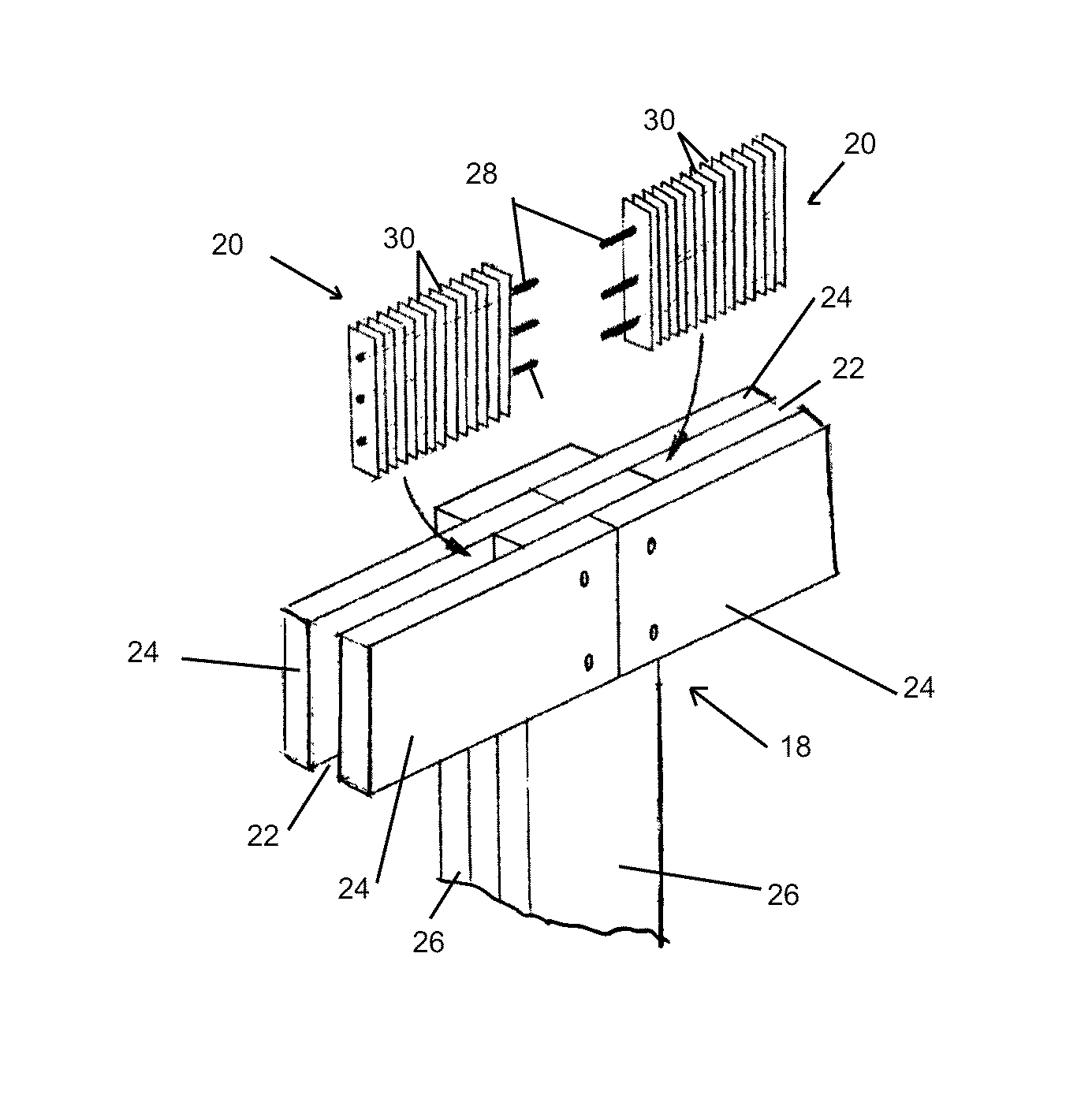
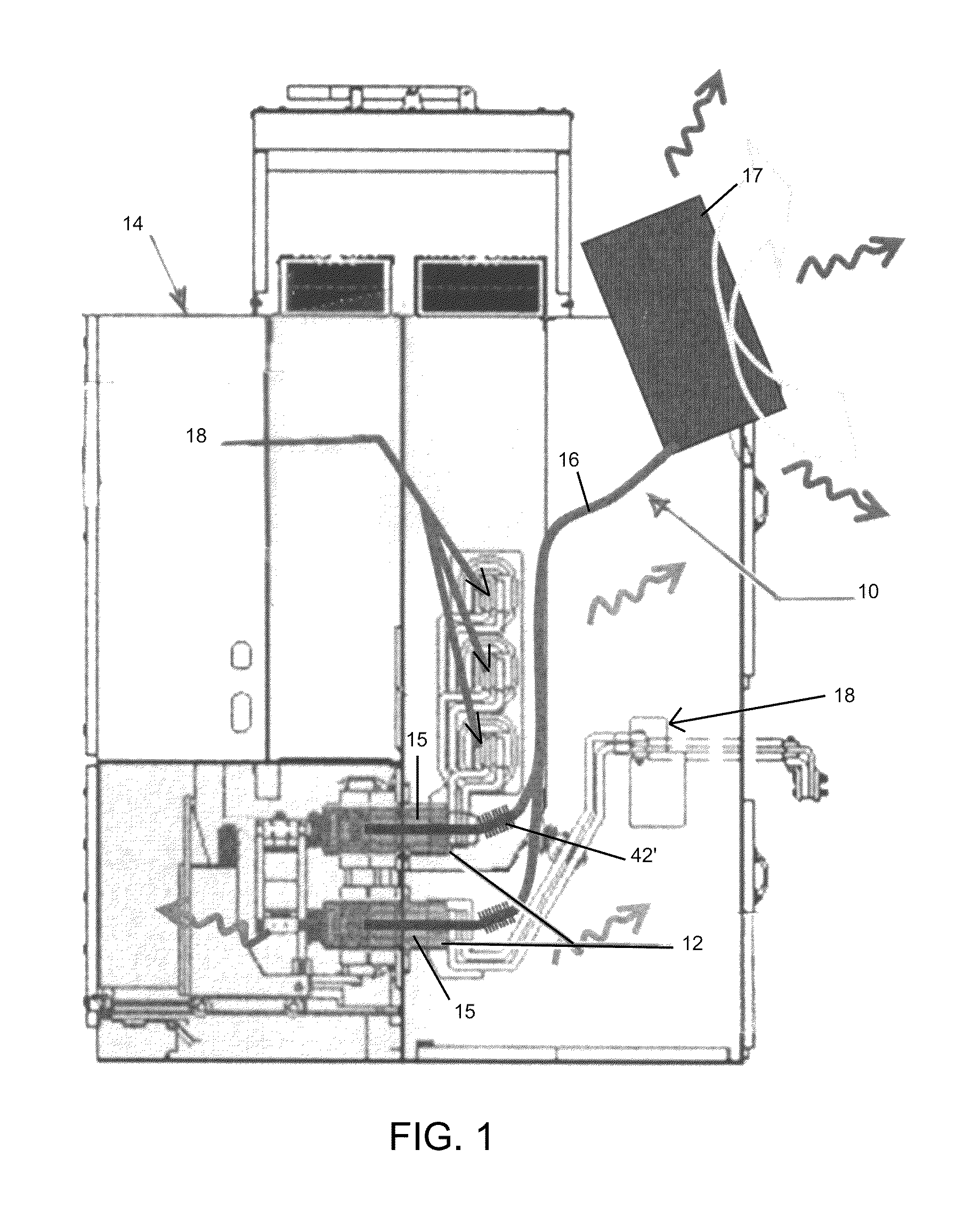
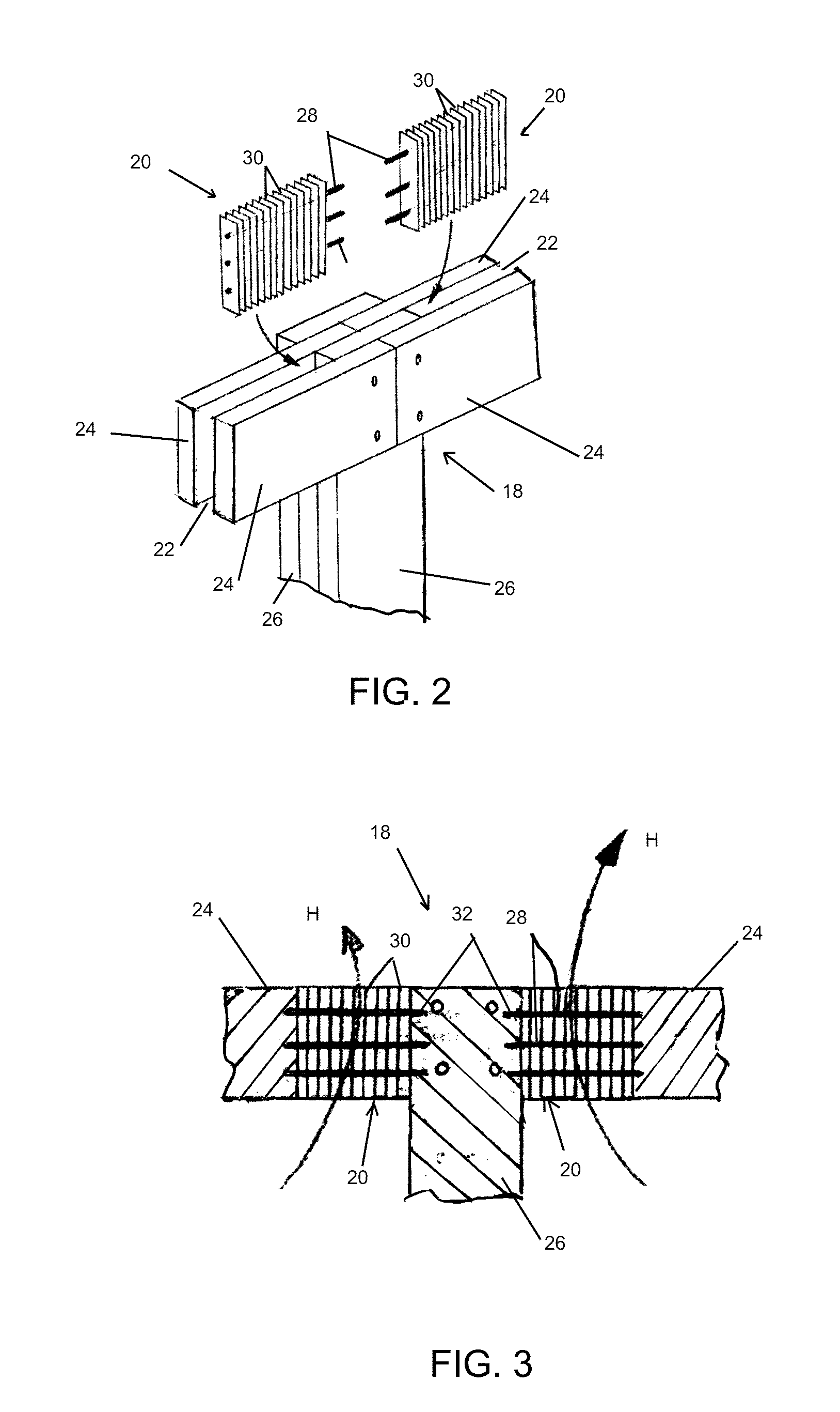
[0017]With reference to FIG. 1, a cooling apparatus in the form of a heat pipe system, generally indicated at 10, is shown as disclosed in commonly owned, co-pending U.S. patent application entitled, “Switchgear Having Evaporative Cooling Apparatus”, Ser. No. 13 / 444,888 the content of which is hereby incorporated by reference into this specification. The heat pipe system 10 is used to efficiently cool the primary contacts 12 without breaching the safety requirements for the self-contained compartments of the switchgear 14. The system 10 includes an evaporator 15 associated with each primary contact 12 and a heat pipe structure 16 coupled between the evaporators 15 and a condenser 17. The condenser 17 is located at a higher elevation than the evaporator 15. Heat of the primary contacts 12 causes working fluid in the evaporator 15 to evaporate and the vapor is directed to the condenser 17. Due to heat exchange with ambient air, the condenser 17 condenses the vapor back to liquid and t...


PUM


Abstract

A cooling apparatus is provided for a switchgear having at least one primary contact to connect to a terminal of a circuit breaker, with a busbar joint connected to the primary contact. The cooling apparatus includes an evaporator associated with the primary contact. A condenser is located at a higher elevation than the evaporator. Heat pipe structure fluidly connects the evaporator with the condenser. Heat transfer structure is coupled with the busbar joint for removing heat from the busbar joint. Working fluid is in the evaporator so as to be heated to a vapor state, with the heat pipe structure transferring the vapor to the condenser and passively returning condensed working fluid back to the evaporator for cooling the at least one primary contact.

Description

FIELD[0001]The invention relates to switchgear circuit breakers and, more particularly, to a cooling apparatus that enhances cooling of additional hotspot along the current path.BACKGROUND[0002]Switchgear configurations have current limits based on the heat rise over ambient room temperature. It is generally desired to limit the maximum temperature of the hottest spot on the switchgear main bus to 105° C. (a rise of 65° C. over an assumed ambient temperature of 40° C.), as directed by the standard IEEE 37.20.2. Typical medium and high-voltage metal-clad switchgear arrangements have maximum continuous current ratings of about 3000 A, due to heat generation. It is desirable to increase this current rating to about 4000 A.[0003]Since these switchgears must be arcing fault resistant, it is exceedingly difficult to dissipate heat losses caused by the nominal currents inside the switchgear compartments. Currently heat losses are dissipated either by radiation and convection from the curre...

Claims


Application Information

Patent Timeline
Patent Type & Authority Patents(United States)
IPC IPC(8): H05K7/20
CPCH01H9/52H01H2009/523H01H2009/526H02G5/10
Inventor KAUFMANN, PATRIKMOLITOR, FRANCOISE
Owner ABB (SCHWEIZ) AG
Why Eureka
Try Eureka