
Domestic appliance

a technology for cooking appliances and ovens, applied in baking, electric heating for furnaces, food science, etc., can solve the problem of increasing the intensity of the illumination of the toasting chamber during the day, and achieve the effect of improving the degree of browning of the toasted foodstuffs

Active Publication Date: 2014-05-13
DYSON TECH LTD
View PDF23 Cites 11 Cited by
  • Summary
  • Abstract
  • Description
  • Claims
  • Application Information

AI Technical Summary

Benefits of technology

[0007]It is an aim of at least the preferred embodiment of the present invention to provide a toasting appliance in which the technique for detecting the degree of browning of the toasted foodstuff is improved.
[0010]The intensity of the light emitted from the second light source is varied during the toasting operation. During a first period of the toasting operation, in which the heating element does not glow, the intensity of the light emitted from the second light source may be maintained at a relatively high value by the controller. As the heating element begins to glow, the intensity of the light emitted from the second light source may be reduced gradually or stepwise to a lower value by the controller. The illumination of the optical receiver by a combination of light which has (i) been emitted from the heating element and reflected by the foodstuff towards the optical receiver and (ii) been emitted the second light source, can be thus maintained at a relatively constant value during the toasting operation.
[0013]The first light source may be located within a first light guide for conveying light to the toasting chamber, and the second light source may be located within a second light guide for conveying light from the toasting chamber. The use of light guides, such as light pipes, for conveying light to and / or from the toasting chamber can enable the more temperature-sensitive components of the optical system to be spaced from the hot toasting chamber, which may reach temperatures in excess of 700° C. during a toasting operation.
[0015]The light sources are preferably arranged to emit strobed light to reduce interference effects from ambient illumination sources, such as fluorescent lighting, on the browning detection. The optical receiver is preferably a photodiode, a phototransistor or a light dependent resistor for receiving strobed light reflected from the foodstuff.
[0016]At least part of the optical system is preferably moveable relative to the carriage. Moving at least part of the optical system relative to the carriage, and thus towards and away from a foodstuff located within the toasting chamber, can enable the intensity of the illumination of the foodstuff to be substantially constant irrespective of the thickness of the foodstuff, and can enable the optical system to be located in close proximity to the foodstuff, increasing the sensitivity of the optical system to changes in the colour of the foodstuff during toasting.
[0017]The heating element is preferably moveable towards and away from the carriage. Moving the heating element towards the carriage can ensure that the heating element is in close proximity to the foodstuff to be toasted during a toasting operation irrespective of the thickness of the foodstuff, enabling the required degree of browning to be achieved rapidly. Said at least part of the optical system may be conveniently mounted for movement with the heating element. Alternatively, separate mechanisms may be provided for moving the heating element and said at least part of the optical system. As another alternative, the heating element may be stationary, and a mechanism may be provided for moving said at least part of the optical system relative to the carriage by an amount depending on the thickness of the foodstuff located therein.

Problems solved by technology

A problem associated with this technique for detecting the degree of browning of the toasted foodstuff is that the intensity of the illumination of the toasting chamber will tend to increase during a toasting operation.

Method used


Image

  • Domestic appliance
  • Domestic appliance
  • Domestic appliance

Examples


Embodiment Construction

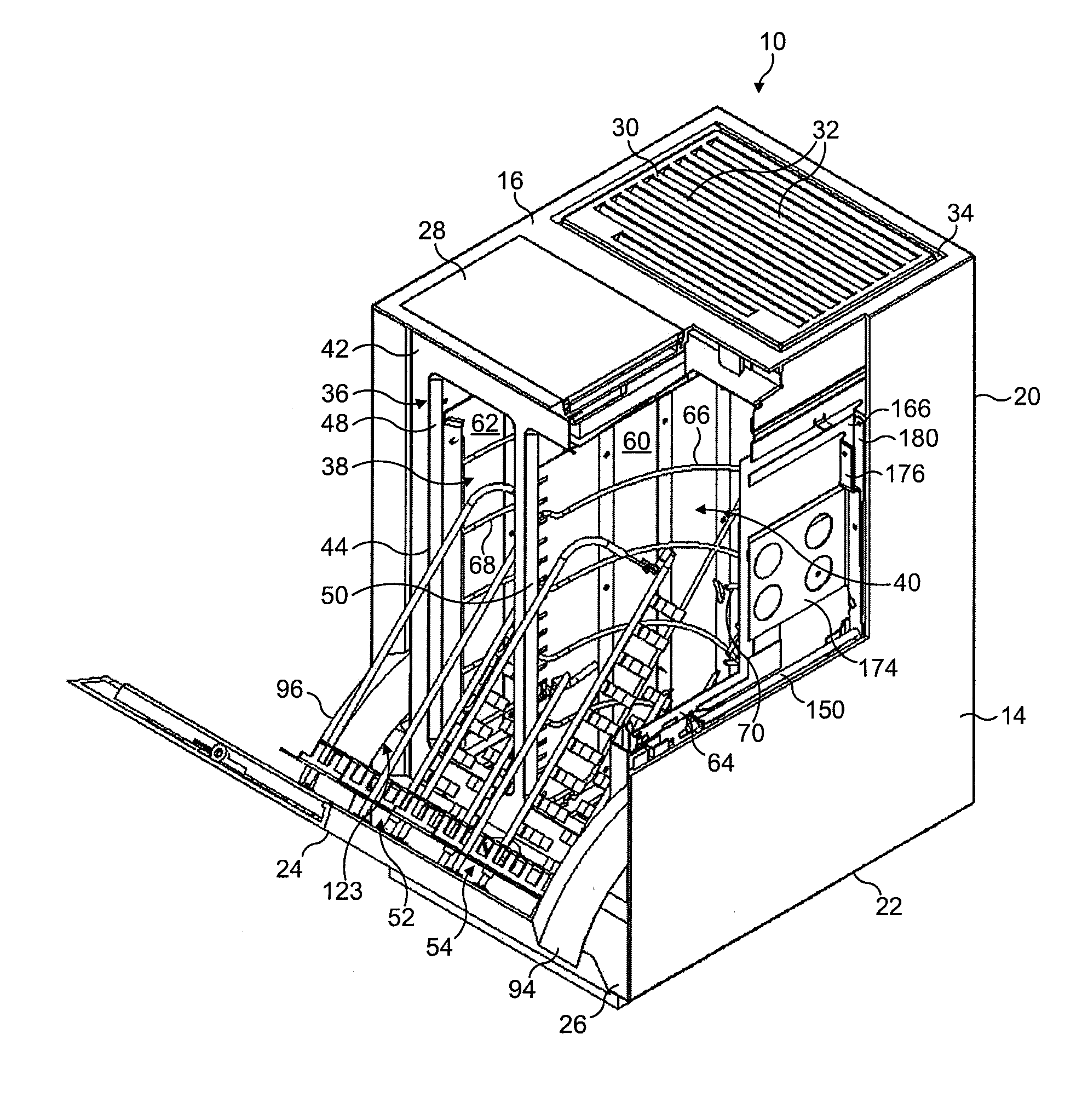
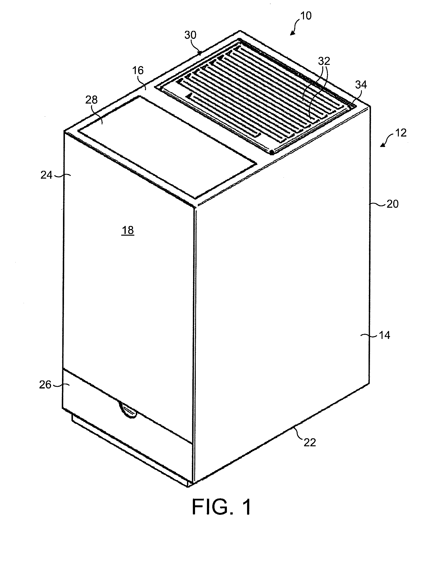
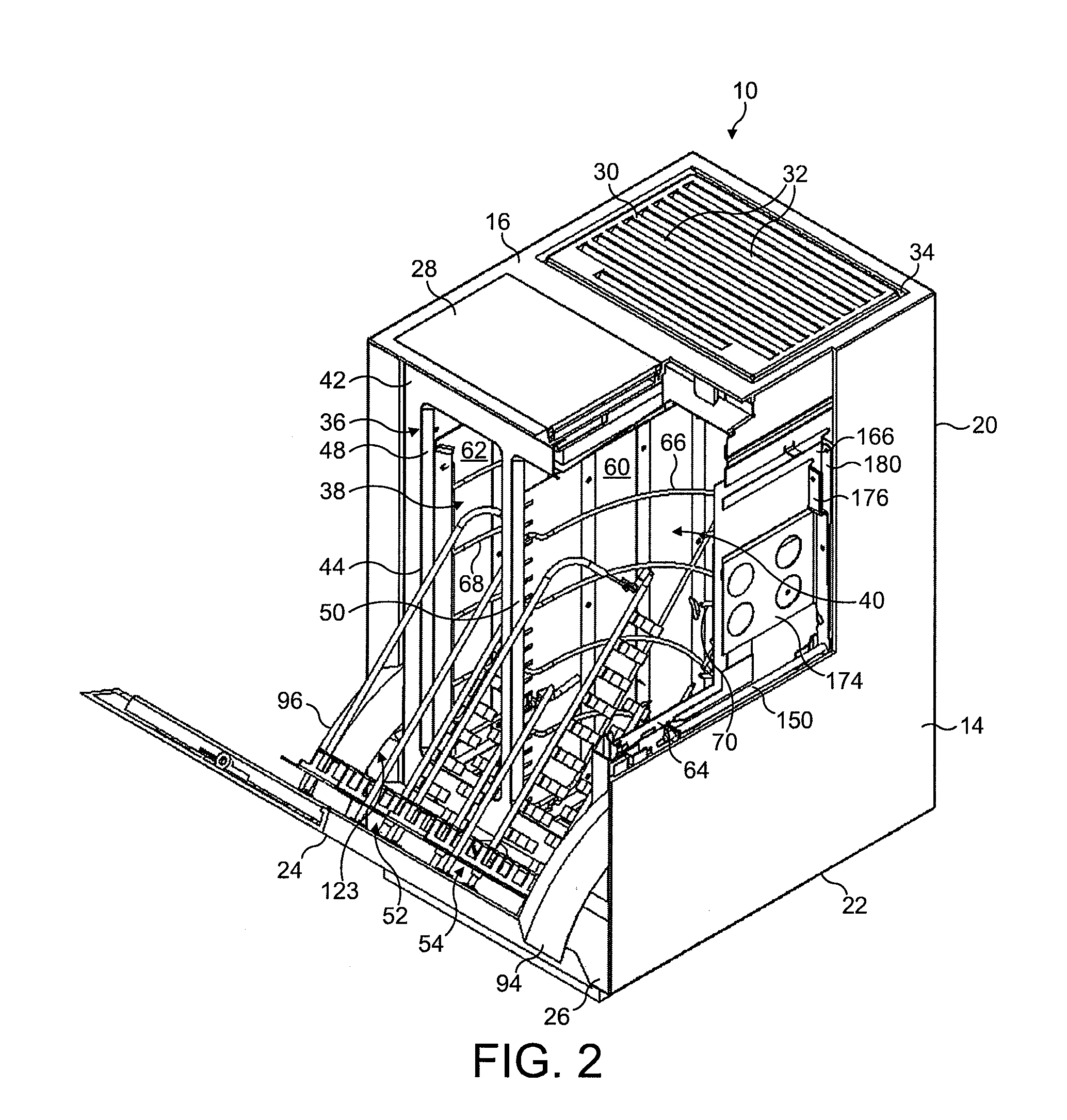
[0038]With reference to FIGS. 1 to 3, a toasting appliance is shown in the form of a domestic electric toaster 10. The toaster 10 comprises an outer cabinet 12 having two side surfaces 14 and, extending between the side surfaces 14, an upper surface 16, a front surface 18, a rear surface 20 and a base 22. In this example, each of the side, front, and rear surfaces 14, 18, 20 is substantially flat, with the cabinet 12 being generally in the shape of cuboid, or right parallelepiped. Although the edges between adjoining surfaces of the cabinet 12 may be chamfered, it is preferred that the radius of each chamfer is less than 1 mm, preferably around 0.75 mm.

[0039]A substantial part of the front surface 18 comprises a door 24. The door 24 is arranged to pivot downwardly and away from the upper surface 16 of the cabinet 12 when moving from a closed position, as shown in FIG. 1, to an open position, as shown in FIGS. 2 and 3. The front surface 18 of the cabinet 12 further comprises the fron...


PUM


Abstract

A toasting appliance includes a toasting chamber, a heating element for heating a foodstuff located within the toasting chamber, an optical system having a first light source for illuminating the foodstuff with light having a first wavelength and an optical receiver for detecting light reflected from the foodstuff. A second light source is provided for illuminating at least the optical receiver with light having a second wavelength different from the first wavelength. A controller varies the intensity of the light emitted from the second light source during a toasting operation.

Description

REFERENCE TO RELATED APPLICATION[0001]This application claims the priority of United Kingdom Application No. 0811367.2, filed Jun. 20, 2008, the contents of which are incorporated herein by reference.FIELD OF THE INVENTION[0002]This invention relates to a toasting appliance, such as a domestic electric toaster.BACKGROUND OF THE INVENTION[0003]A domestic electric toaster typically comprises a toasting chamber into which slices of bread or other toastable foodstuffs are introduced, a source of radiant heat in the form of a plurality of electric heating elements and a cabinet housing these components. A carriage is provided in order to assist the user in inserting and removing the bread. Conventionally, domestic toasters have slots in their upper surface into which bread may be inserted. The carriage is then lowered vertically, the heating elements are energised and the bread is toasted. At the end of the toasting operation, the carriage is raised so that the toast protrudes upwardly f...

Claims


Application Information

Patent Timeline
Patent Type & Authority Patents(United States)
IPC IPC(8): A47J37/08
CPCA47J37/085
Inventor DOUGLAS, PAUL GRAHAMBYRNE, KEVIN PAULPARSONS, ADRIAN ANTHONY
Owner DYSON TECH LTD
Learn More