Tool clamping device

a clamping device and tool technology, applied in the direction of turning apparatuses, metal-working holders, supports, etc., can solve the problem of time gain for each completed par

Inactive Publication Date: 2014-05-13
OTT JAKOB & SPANNTECHN
View PDF15 Cites 2 Cited by
  • Summary
  • Abstract
  • Description
  • Claims
  • Application Information

AI Technical Summary

Benefits of technology

[0008]According to the invention, the position of the tool release piston is detected by a sensor that is integrated structurally into the tool clamping device. This measure solves the problem that a use of readily available position sensors for hydraulic or pneumatic cylinders is decisively prevented by the special spatial conditions of a tool clamping device specified for installation in an operating spindle, such as, in particular, the presence of a rotating lubricant feed. The function further provided according to the invention of the tool release piston as a direct component of an electrical component guarantees, on one hand, the functional reliability of the position detection and simplifies, on the other hand, the construction of the sensor. Advantageous effects of the invention include a reduction in unplanned spindle standstill times or a reliable cycle sequence during the tool exchange. In addition, through the feedback of the piston position, sequence optimizations are possible that can lead to a time gain for each completed part.
[0009]A first embodiment of the invention consists of an electrical switch in which the tool release piston closes an electrical contact through a mechanical contact with an end-face contact and here acts as a contact electrode or at least as part of such a contact electrode, that is, conducts the current flowing in the case of a closed switch.
[0010]A second embodiment of the invention consists of an electrical capacitive element in which a section of the tool release piston acts as a capacitor electrode due to its metallic conductivity. Through a cross-sectional change of the above section along the movement direction of the piston, a dependency of the electrode distance and thus of the capacitance value on the piston position can be achieved.
[0011]A third embodiment of the invention consists of an electrical inductive element in which a section of the tool release piston made, in this case, from ferromagnetic material, acts as a magnetic core. Through a cross-sectional change of the above section along the movement direction of the piston, a dependency of the distance between a coil and the magnetic core allocated to this coil and thus of the inductance value on the piston position can be achieved.BRIEF DESCRIPTION OF THE FIGURES

Problems solved by technology

In addition, through the feedback of the piston position, sequence optimizations are possible that can lead to a time gain for each completed part.

Method used


Image

  • Tool clamping device
  • Tool clamping device
  • Tool clamping device

Examples


first embodiment

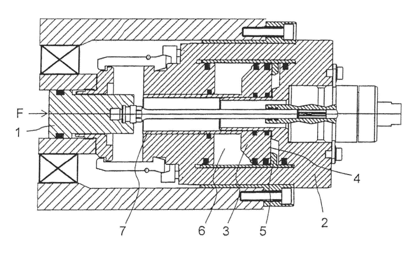
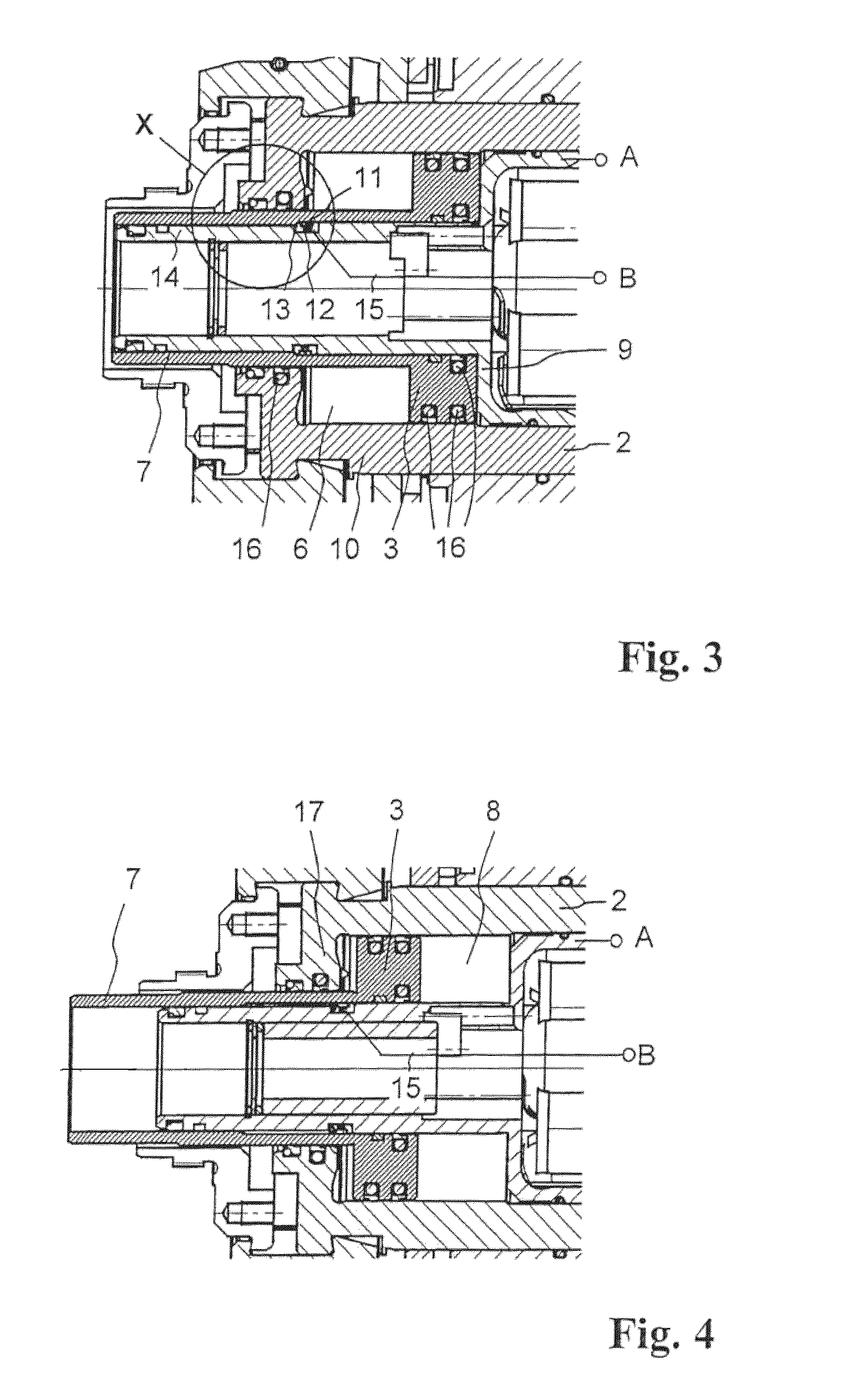
[0026]a tool clamping device according to the invention with a sensor for detecting the position of the tool release piston is explained below with reference to FIGS. 3 to 5. Here, FIG. 3 shows, like FIG. 1 before, a cutout from a tool clamping device of the type forming the basis here. However, relative to FIG. 1, a few components, among these, in particular, the drawbar 1, are left out and therefore the remaining components are shown in detail. According to the invention, the tool release piston 3 functions as a component of an electrical switch, as described below. For forming this switch, the rear wall 9 of the cylinder 2 is contacted electrically and guided to an external connection terminal A. The rear wall 9 of the cylinder 2 is here, in contrast to the schematic diagram of FIG. 1, a part that is separate from the side wall 10, because the cylinder 2 must be open on one side for inserting the tool release piston 3.

[0027]The tool release piston 3 is electrically contacted in t...

second embodiment

[0036]FIG. 7 schematically shows the invention, wherein the partial view of a tool clamping device corresponds to that of FIG. 3, that is, represents the clamped position with the tool release piston 3 in its rear end position. As can be seen in FIG. 7, in the region of the hollow cylindrical section 7 of the tool release piston 3 projecting in the direction of the drawbar, both within and also outside the hollow cylinder, two annular capacitor electrodes 18 and 19 or 20 and 21 are arranged in the axial direction one next to the other and adjacent to each other, wherein there is a specified spacing in the axial direction between the two inner-lying electrodes 18 and 19 and the two outer lying electrodes 20 and 21.

[0037]The capacitor electrodes 18 to 21 are arranged similar to the insulation ring 12 of the first embodiment each in separately formed annular grooves that are not shown for the sake of simplicity in FIG. 7 and are necessarily electrically insulated relative to the guide ...

third embodiment

[0047]FIG. 9 schematically shows the invention, wherein the partial view of a tool clamping device there similarly corresponds to that of FIG. 3, that is, represents the clamped position with the tool release piston 3 in its rear end position. As can be seen in FIG. 9, in the region of the hollow cylindrical section 7 of the tool release piston 3 projecting in the direction of the drawbar both within and also outside the hollow cylinder, a coil 24 or 25 is present at a specified mutual axial spacing.

[0048]The coils 24 and 25 are arranged just like the insulating ring 12 of the first embodiment in separately formed annular grooves that are not shown in FIG. 9 for the sake of simplicity. Through the use of highly permeable material as the coil body, i.e., covering the mentioned grooves with such material, penetration of the magnetic field into the surrounding material of the guide body 14 can be largely prevented in order to improve the intended measurement effect described below. As ...


PUM

PropertyMeasurementUnit
electrically conductiveaaaaaaaaaa
capacitanceaaaaaaaaaa
total capacitanceaaaaaaaaaa

Abstract

In the case of a tool clamping device, in particular, for an operating spindle of a processing machine, with an activation element (3) that can be moved by a drive between a first position, in which the tool clamping device is located in a clamped position, and a second position, in which the tool clamping device is located in a released position, a sensor is present in the form of at least one electrical component for detecting a position of the activation element (3). The sensor is integrated structurally into the tool clamping device and at least one section of the activation element (3) directly forms a component of the one or more electrical components, wherein its position influences an electrical property of this component. The component can be an electrical switch whose closed state depends on the position of the activation element (3) in that at least one section of the activation element (3) is electrically conductive and forms a contact electrode of the switch or a part of such an electrode. However, it could also be a capacitor or an inductor.

Description

CROSS REFERENCE TO RELATED APPLICATION[0001]This application claims priority under 35 U.S.C. §119 to German Patent Application No. 10 2008 058 185.2 filed Nov. 20, 2008, the entire contents of which are incorporated herein by reference.FIELD OF THE INVENTION[0002]The invention relates to a tool clamping device.BACKGROUND OF THE INVENTION[0003]DE 100 43 006 C1 teaches a device. Here an assembly of plate springs provides a tensile force for clamping a tool or tool holder in a tool mount through a set of collet chuck segments. The tool is released by an axial displacement of a so-called drawbar on which, for this purpose, a corresponding counter force must be applied. This counter force is applied as a compressive force by means of a piston driven hydraulically or pneumatically onto the end face of the drawbar facing away from the tool mount. The piston is therefore designated as a tool release piston. As an alternative, in DE 10 2004 051 031 B3, the use of an electric drive was also p...

Claims


Application Information

Patent Timeline
Patent Type & Authority Patents(United States)
IPC IPC(8): B23Q17/22
CPCB23B31/265B23B2231/26Y10T279/12Y10T409/309408Y10T409/309464Y10T409/104929
Inventor GAST, STEPHANBONERZ, STEFANBECHTELER, WOLFGANG
Owner OTT JAKOB & SPANNTECHN
Why Eureka
Try Eureka