Moving electrode electroflocculation process

a moving electrode and electroflocculation technology, applied in the field of water treatment, can solve the problems of low current efficiency, solutes have a tendency to form scales and foul equipment, and the electroflocculation cells of the art are prone to fouling, so as to minimize the build-up of organic or inorganic deposits

Inactive Publication Date: 2014-05-13
JULIUS BLUM GMBH
View PDF16 Cites 0 Cited by
  • Summary
  • Abstract
  • Description
  • Claims
  • Application Information

AI Technical Summary

Benefits of technology

[0018]This invention is directed to an electroflocculation cell that meet this need. The cell comprises two electrodes, a “top” and a “bottom” electrode having voltages of different polarities and made of iron and / or aluminium which form multivalent salts. Said electrodes are in constant or periodic movement thereby minimizing the build-up of organic or inorganic deposits.
[0025]This new, state-of-the-art, technique is simple. It does not require expensive electrodes, nor does it use sophisticated equipment. Energy requirement is also minimal for there is a higher current efficiency. Another object of the present invention is to provide a high volume, foul-resistant electroflocculation process which uses much less costly equipment. All the problems that are circumvented by this new method are clearly present in all prior disclosed methods of electroflocculation.

Problems solved by technology

A disadvantage of the prior art electroflocculation cells is tendency to foul.
Such solutes have a tendency to form scales and foul the equipment.
Commonly present suspended hydrocarbons, turbidity, colloids, and particles may also form strongly adherend deposits and oil films on the cell electrodes, thereby causing local pitting resulting in low current efficiency.
Practical examination shows that this configuration has a low volume capacitiy and shows a strong tendency to form nonconducting deposits on the electrodes resulting in low current efficiency.
This electroflocculation cell has local stagnant areas prone to fouling and requires costly machining of the electrode stack.
This stream of compressed diminishes fouling of the apparatus, however examination in practice reveals that the current efficiency of this design is poor.
This design however requires one of the electrodes to be of the composite type, something that turns out to be more costly than the use simple electrodes.
Moreover, composite electrodes tend to be unstable due to the different dissolution rates of aluminium and iron.
Despite that the problem has been correctly recognized no practical realization is possible because the electrodes thin out.
Since an additional cleaning mechanism is necessary this proposal becomes very costly.

Method used


Image

  • Moving electrode electroflocculation process
  • Moving electrode electroflocculation process

Examples


example i

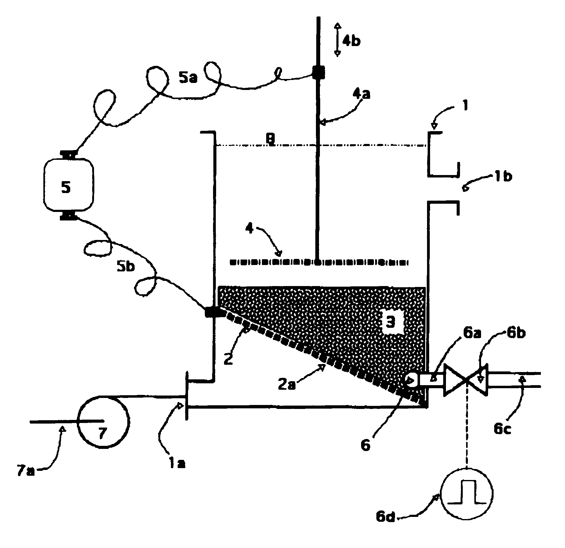
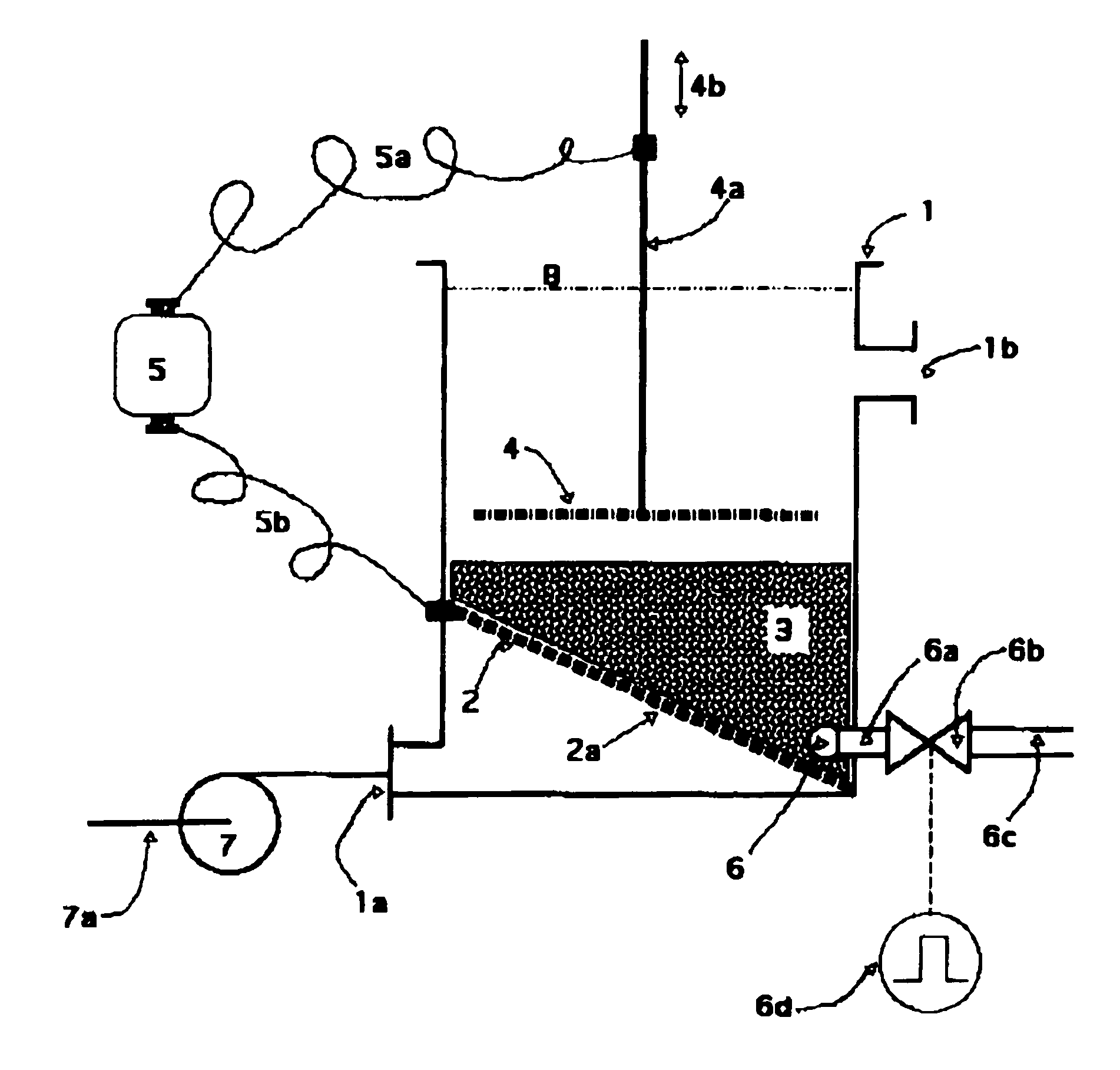
[0045]An electroflocculation cell according FIG. 1 contained as electrode (3) aluminium granules (pellets) of 2-3 mm diameter. This bed of aluminium granules rested on a 5 mm aluminium metal plate as the support (2). The metal plate (2) had various 1 mm diameter openings (2a). The tilting angle of the support (2) was 20 degrees. At the thickest part of the granule bed (3) and attached to the support plate (2) a gas injection tube (6) of 25 mm outer diameter was positioned. This gas injection tube was equipped with a number of tiny openings to permit passage of the gas directed into the granule bed (3). The medium depth of the granule bed was 40 cm.

[0046]Directly above the granule bed electrode (3) an aluminium gridmesh electrode (4) as a 4 mm strong perforated metal plate had been attached via metal rods (4a) to a mechanical vibrator.

[0047]The perforations represented 45% of the metal plate (4).

[0048]Measured submerged, the average vibration amplitude of the gridmesh electrode (4) w...

example ii

[0055]An electroflocculation cell according FIG. 1 contained as electrode (3) iron granules of 1-3 mm diameter. This bed of granules rested on a 6 mm steel plate as the support (2). The steel plate (2) had various plastic nozzles with 0.7 mm openings (2a). The tilting angle of the support (2) was 28 degrees. At the thickest part of the granule bed and attached to the support plate (2) a gas injection tube (6) of 20 mm outer diameter was positioned. This gas injection tube was equipped with a number of tiny openings to permit passage of the gas directed into the granule bed (3). The medium depth of the granule bed was 60 centimeters.

[0056]Directly above the granule bed electrode (3) an rib mesh electrode (4) made from 8 mm diameter steel wire had been attached via metal rods (4a) to a mechanical vibrator.

[0057]The perforations represented 85% of the electrode area (4).

[0058]Measured submerged, the average vibration amplitude of the rib mesh electrode (4) was 2 mm. Vibration frequency...


PUM

PropertyMeasurementUnit
tilt angleaaaaaaaaaa
tilting angleaaaaaaaaaa

Abstract

The present invention provides a high volume, foul-resistant electrolytic process for treating contaminated water comprising at least one upflow electroflocculation cell consisting of (i) a lower (or “bottom”) electrode (3) in form of a porous, non-fluidized bed of loose iron or aluminium granules kept in periodic motion by pulsed gas injections and (ii) an upper (or “top”) vibrating electrode (4) made of an iron or aluminium grid mesh or ribmesh. A voltage potential between the upper (4) and lower (3) electrode causes ions to be released from the moving electrodes. These ions oxydise and / or render insoluble contaminants in the ascending flow of wastewater and create easy filterable insoluble contaminants resulting in substantially cleansed water. Such moving electrodes electroflocculation cells are useful at municipal water works and commercial and industrial applications were large amounts of raw water have to be processed.

Description

REFERENCES CITED[0001]German Patent DE 3641 365 (1988) Klose; G.[0002]European Patent EP 6682 44 (1994) Batt; S.[0003]PCT / WO. 95 / 15295 (1995) Beaujean; H.[0004]U.S. Pat. No. 6,179,991 (2001) Norris; B.[0005]U.S. Pat. No. 6,663,766 (2003) Adin; A.OTHER REFERENCES[0006]Matteson, Michael J., Dobson, Regina L. et al., Electrocoagulation and separation of aqueous suspensions of ultrafine particles, Colloids and Surfaces A: Physicochemical and Engineering Aspects, 104; 1 (November): 101-109 (1995).[0007]Vik, E A, Carlson, D A, Eikun, A S and Gjessing, E T, Electrocoagulation of potable water, Water Research, 18; 11: 1355-1360 (1984).FIELD OF THE INVENTION[0008]This invention relates to water treatment and relates particularly, though not exclusively, to treating polluted water using electroflocculation and / or electrocoagulation reactions.BACKGROUND OF THE INVENTION[0009]Electroflocculation cells have been described in the prior art (see for example German Patent DE 3,641,365 to Klose, U.S...

Claims


Application Information

Patent Timeline
Patent Type & Authority Patents(United States)
IPC IPC(8): C02F1/461C02F1/465C02F1/463
CPCC02F2001/46161C02F2001/46133C02F2201/4619C02F2001/46123C02F1/46114C02F1/463
Inventor BLUM
Owner JULIUS BLUM GMBH
Why Eureka
Try Eureka