Magnetic clamps for laboratory shakers

a magnetic clamp and shaker technology, applied in the field of laboratory products, can solve the problems of metal clamps, substantial damage, and flasks that spin within, and achieve the effect of avoiding the hassle of removal and simplifying installation

Active Publication Date: 2014-05-13
LABSTRONG CORP
View PDF4 Cites 13 Cited by
  • Summary
  • Abstract
  • Description
  • Claims
  • Application Information

AI Technical Summary

Benefits of technology

[0005]In one aspect, the invention pertains to a flask clamp that uses permanent magnets to attach the flask clamp to the shaker platform thus allowing the flask clamp to be easily removed from the platform without the use of tools. The clamp simplifies installation, as well as cleaning, autoclaving and configuration changes. Moreover, the invention allows the user to use one platform in the laboratory, and thus avoids the hassle of removing and storing several platforms with flask clamps screwed thereto.
[0006]In its preferred form, the clamp has a generally circular base constructed of two generally circular plates. One or more permanent magnets are attached and exposed below the base, preferably three nickel-coated, rare earth magnets equally spaced around the periphery of the base. The top circular base plate is desirably magnetic, e.g. non-magnetized stainless steel. The bottom circular plate includes holes through which the rare earth magnets extend. The bottom base plate with the magnet holes is desirably made of a non-magnetic material, such as non-magnetic stainless steel. The nickel-coated, rare earth magnets are preferably flat magnets, and the flat bottom surface of the magnets (as well as a magnetic base plate) are magnetically attracted to the shaker platform, which is preferably made of magnetic, non-magnetized stainless steel. The nickel coating helps to protect the rare earth magnets from corrosion and chipping and also provides an improved surface for adhesion of the magnets to the clamp base. In addition, the use of a nickel coating does not compromise the viability of biological cells in the laboratory, as would for example a zinc coating.
[0007]The base of the flask clamp also includes downwardly extending positioning bosses, for example three positioning bosses made of engineered thermal plastic such as polyoxymethylene. The downwardly extending bosses are sized and configured to fit into clamp positioning holes or indentations on the shaker platform when the flask clamp is positioned on the shaker platform with the magnets exerting magnetic pressure to hold the flask clamp on the shaker platform. The positioning bosses prevent the flask clamp from sliding on the surface of the shaker platform while the shaker is in use. The clamp positioning holes or indentations on the shaker platform are preferably non-threaded such that the positioning bosses can be easily set in the holes or indentations without a tool.

Problems solved by technology

One of the issues with metal clamps of that flasks tend to spin within the clamps when the shaker operates.
The spinning can cause marring if the flask is made of glass, and in fact can cause substantial damage if the flask is made of plastic.
Another issue is that metal springs require extreme forces to insert or remove the flask, and there is the danger of flask breakage.
In addition, the metal springs tend to deform and loosen after repeated use and the flasks tend to rattle loosely inside the metal flask clamp creating significant noise pollution in the workspace.
If the flask contains a large volume of fluid significant torque is generated which can cause the flask to spin excessively within the clamp especially if the metal springs are loose.
Plastic clamps have been offered in the industry, but have not been widely accepted primarily because they do not conform well to the flask.
In addition, it is inconvenient for laboratory workers to detach and replace the clamps because the clamps are screwed to the shaker platform.
As such, reconfiguring the clamp arrangement on the platform can be quite time consuming.
Storage can be an issue because space in the laboratory is often limited.

Method used


Image

  • Magnetic clamps for laboratory shakers
  • Magnetic clamps for laboratory shakers
  • Magnetic clamps for laboratory shakers

Examples


first embodiment

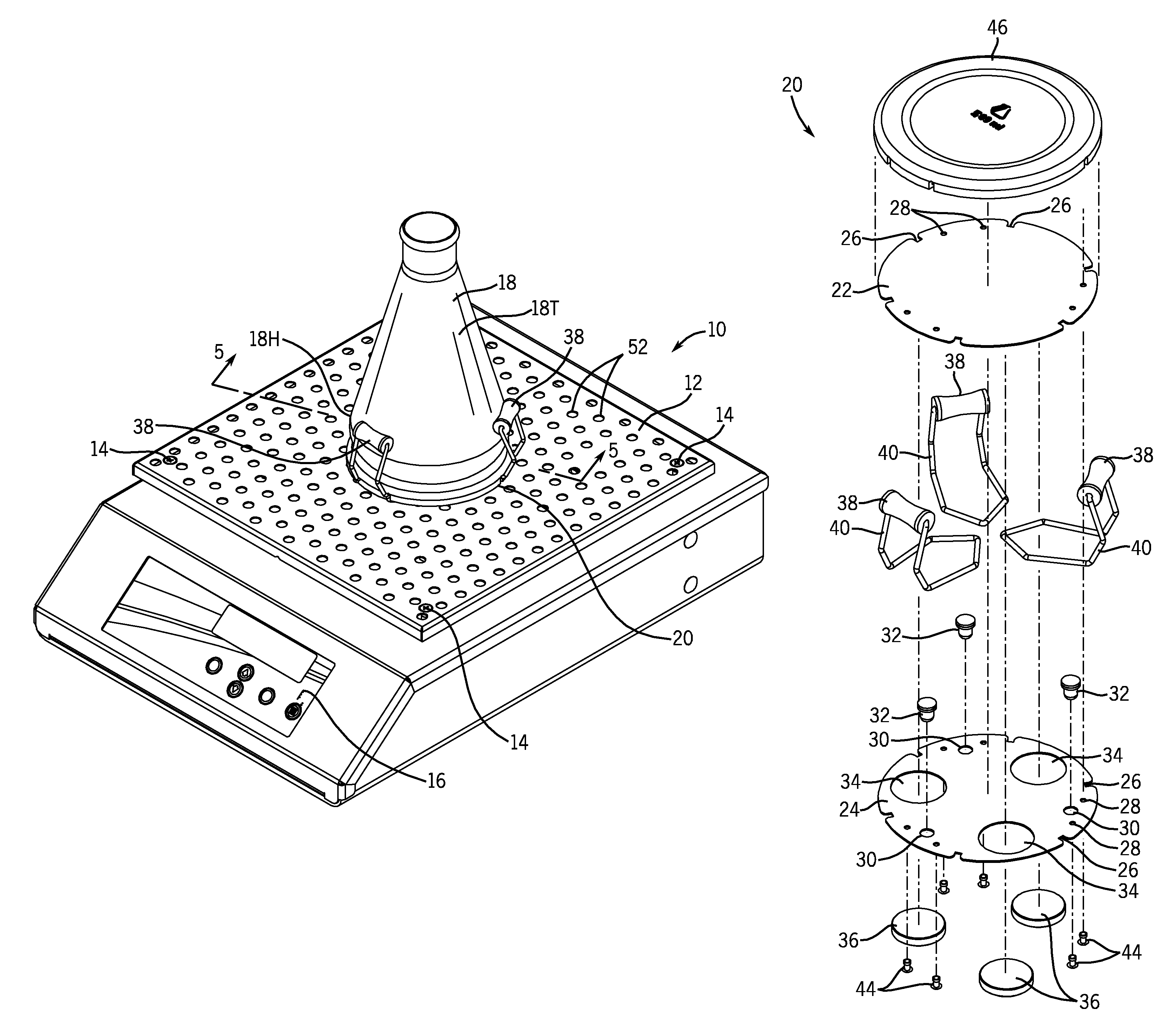
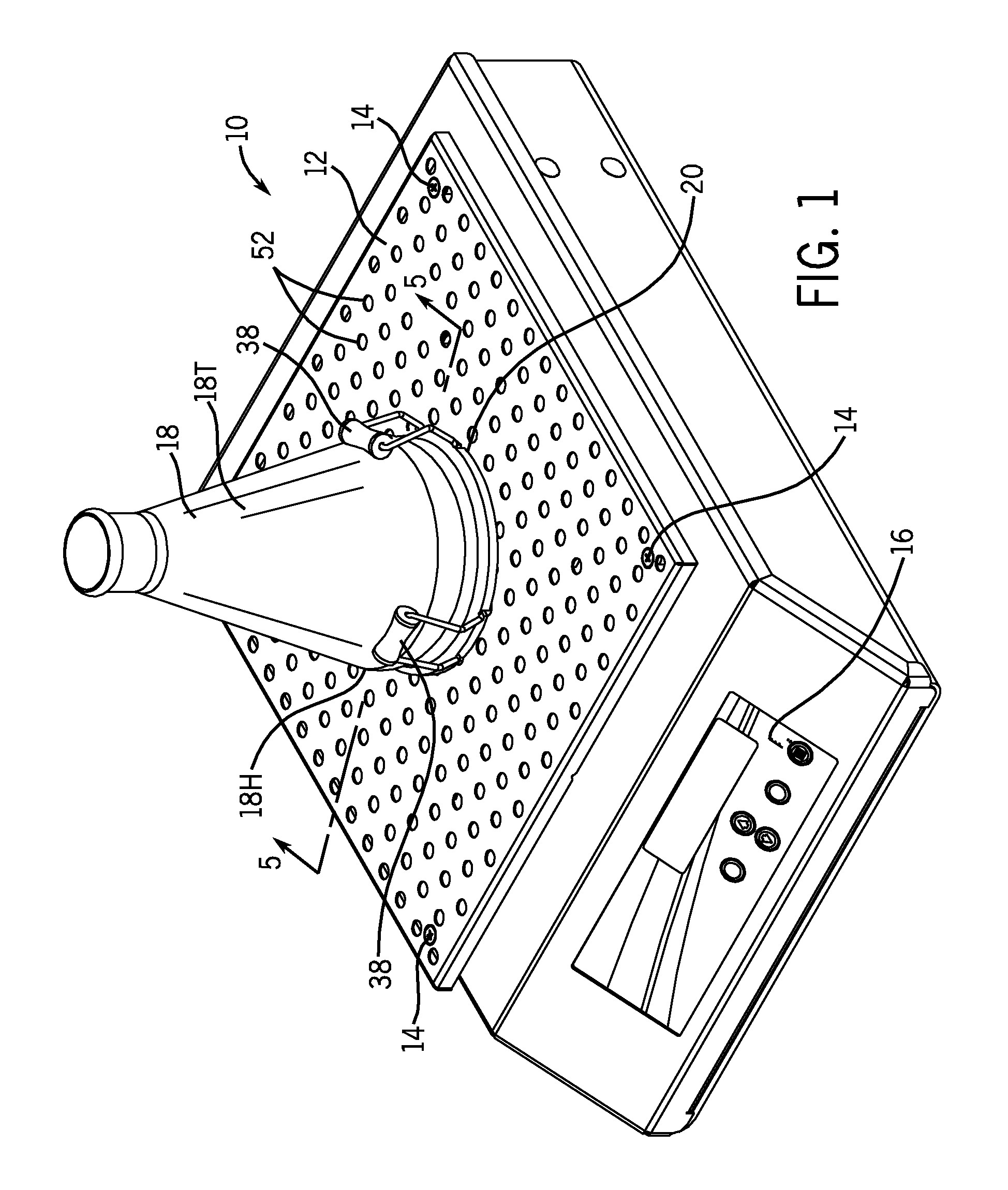
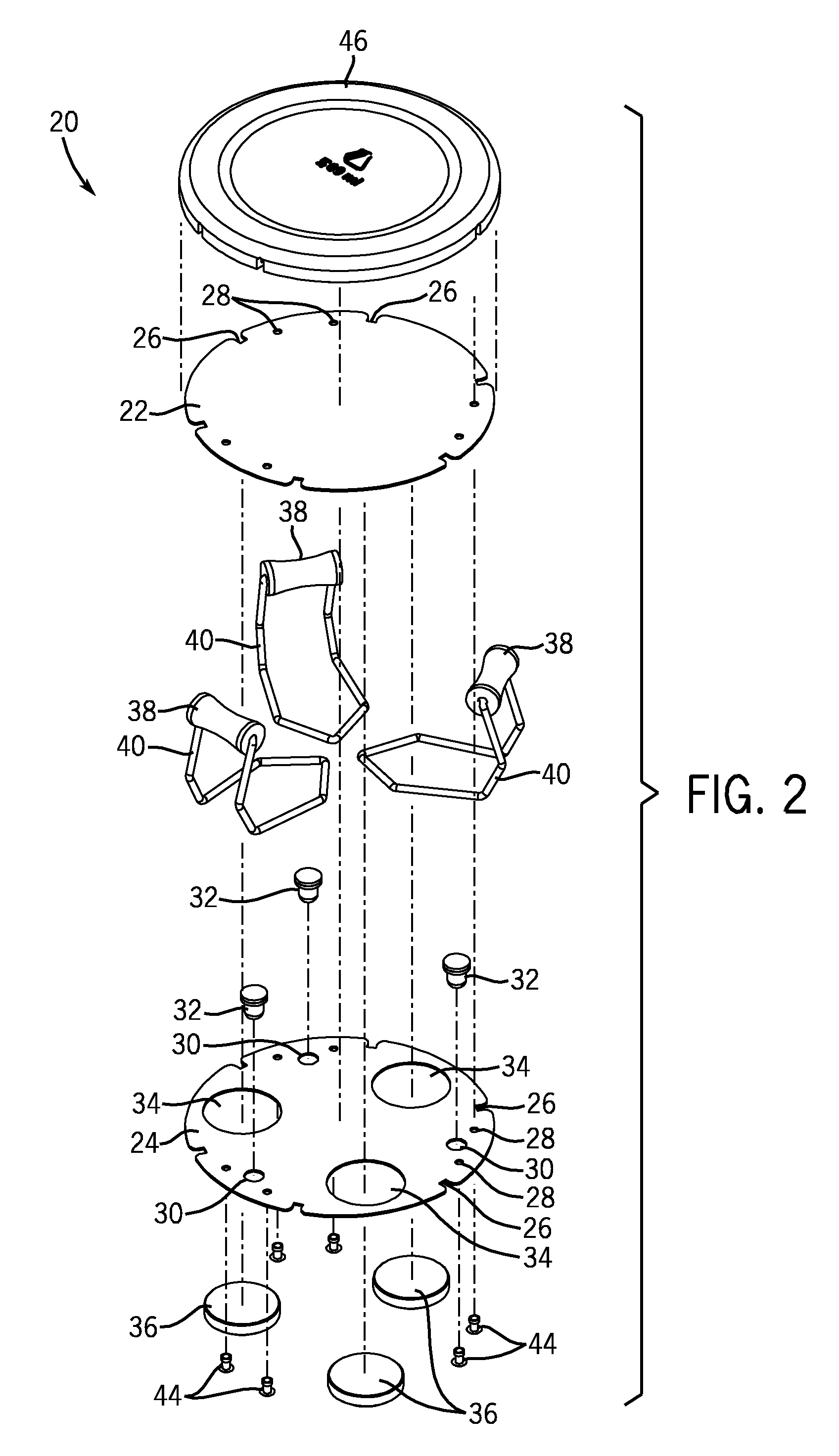
[0031]Referring now to FIGS. 2-4, the flask clamp 20 in the invention has a top base plate 22 and a bottom base plate 24. The top base plate 22 is preferably made of magnetic stainless steel so that permanent magnets are attracted to plate 22. It is desirable that both base plates 22, 24 remain rigid, flat and even during construction and in use. The exemplary flask clamp 20 is a 500 ml flask clamp, and for this size of flask clamp a plate thickness of 0.038″ has been found to be suitable for the base plates 22 and 24. The top base plate 22 is generally circular in shape, but contains three pairs of notches 26 around its peripheral edge. The top base plate 22 also includes rivet holes 28. The bottom base plate 24 is generally the same size as the top base plate 22. Like the top base plate 22, the bottom base plate 24 includes rivet holes 28. As shown in FIG. 2, the bottom base plate 24 also includes notches 26 as shown in the top base plate 22. The bottom base plate 24 includes thre...

second embodiment

[0039]FIGS. 6 through 9 illustrate a flask clamp constructed in accordance with the invention. In many respects, the flask clamp 120 as illustrated in FIGS. 6-9 is similar to the flask clamp 20 described in FIGS. 2-5. The flask clamp 120 shown in FIGS. 6-9, however, is designed to accommodate larger flasks, such as a flask having a volume of 1000 ml. The flask clamp 120 includes spring fingers 140 and roller sets 138 designed to accommodate larger sized flasks than the bent wire form configuration illustrated in connection with the flask clamp 20 shown in FIGS. 2-5.

[0040]The flask clamp 120 in FIGS. 6-9 includes a top base plate 122 made of a magnetic stainless steel, and a bottom base plate 124 made of non-magnetized spring stainless steel. The bottom base plate 124 includes openings 134 for the magnets 136 as in the other embodiment as well as openings for the positioning bosses 132. In the flask clamp 120 shown in FIGS. 6-9, the spring fingers 140 are made of spring stainless ste...

third embodiment

[0043]FIGS. 10-13 illustrate the invention in which the clamp 220 is configured to hold a test tube rack 218. The clamp 220 has a substantially rectangular bottom base plate 224 made of a non-magnetic material such as non-magnetic steel. The bottom base plate 224 includes holes 234 for the magnets 236. It also includes holes for the positioning bosses 232 and for stabilizing feet 231. Integral with the bottom base plate 224 are upstanding walls 271 which include openings for mounting the other components of the clamp 220 for holding the test tube rack 218. A top base plate 222 is made of a magnetic steel material. As in the other embodiments, the magnets 236 pass through the openings 234 in the bottom base plate 224 and are attached, e.g. by adhesive or otherwise, to the top base plate 222. The top base plate 222 is attached to the bottom base plate 224 once the positioning bosses 232 and the stabilizing feet 231 are in place via screws 223 and nuts 225. A resilient finger member 24...


PUM

PropertyMeasurementUnit
temperaturesaaaaaaaaaa
volumeaaaaaaaaaa

Abstract

A clamp for an Erlenmeyer flask or other laboratory containers or racks uses nickel-coated, rare earth magnets to secure the clamp to a platform for a laboratory shaker. The base of the clamp has downwardly extending positioning bosses that seat in holes or indentations on the shaker platform to prevent horizontal sliding of the clamp when the shaker is in use. A removable and replaceable, elastomeric cover for the base of the flask clamp provides cushioning and prevents spinning of the flask when the shaker is in use.

Description

FIELD OF THE INVENTION[0001]The invention pertains to laboratory products and in particular to clamps for laboratory shakers.BACKGROUND OF THE INVENTION[0002]Shakers are widely used in laboratories to stir liquids held in beakers, flasks or test tubes. The shaker has a platform that oscillates horizontally when the shaker is operating. A shaker platform will normally include an array of threaded holes to enable attachment of clamps to the platform with screws. Metal flask clamps for Erlenmeyer flasks typically include a pair of intersecting bands that extend horizontally to form a base and bend upward to extend above the hip of the flask and along the tapered wall of the flask. Normally, a spring coil is attached around the ends of the bent bands. The flask is inserted into the clamp by expanding the spring coil and the bands outwardly by pressing the base of the flask into the opening created by the spring coil. One of the issues with metal clamps of that flasks tend to spin within...

Claims


Application Information

Patent Timeline
Patent Type & Authority Patents(United States)
IPC IPC(8): B01L9/04
CPCB01L9/50Y10T29/49826
Inventor LOCKWOOD, MARK D.LOEFFELHOLZ, MARK G.
Owner LABSTRONG CORP
Why Eureka
Try Eureka