Capacitive touch control sensor

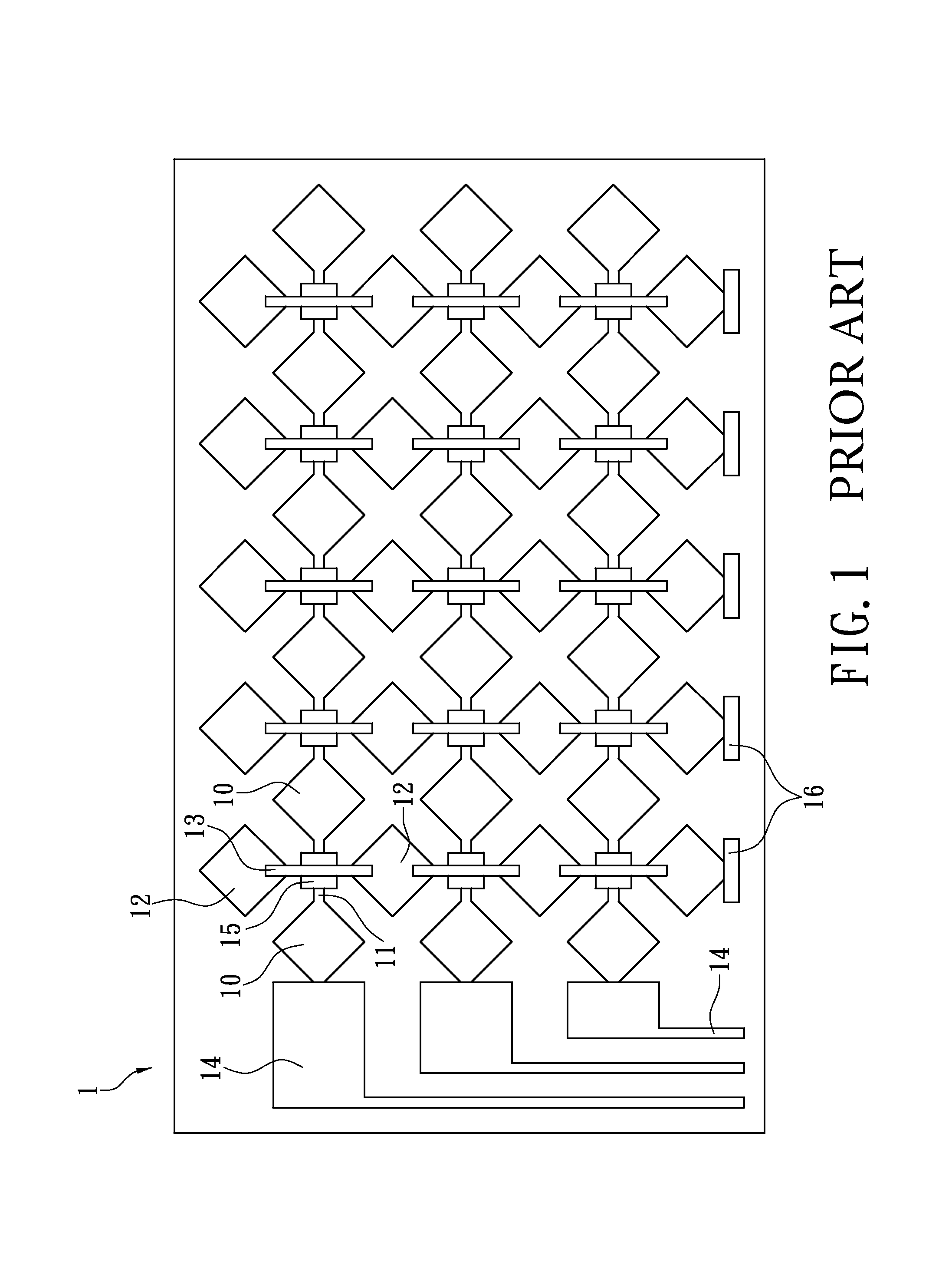
a capacitive touch control and sensor technology, applied in the direction of electronic switching, instruments, pulse techniques, etc., can solve the problems of high production cost and complex fabrication of conventional multi-layer capacitive touch control sensors b>1/b>, and achieve the effect of reducing production costs and a larger touch screen

Inactive Publication Date: 2014-05-13
J TOUCH CORPORATION
View PDF3 Cites 3 Cited by
  • Summary
  • Abstract
  • Description
  • Claims
  • Application Information

AI Technical Summary

Benefits of technology

[0005]The present disclosure provides a capacitive touch control sensor having electrode arrangement that is compact and requires lower production cost. In addition, the arrangement of the first and second electrode wires allows relatively larger touch screen.
[0007]The instant disclosure is a single-layered capacitive touch control sensor and the first and second electrodes together with the first and second electrode wires can be disposed in a single production without the complex multiple procedure. Hence the capacitive touch control sensor has lower fabrication cost and lighter volume.

Problems solved by technology

As can be seen, the fabrication of the conventional multilayer capacitive touch control sensor 1 is complex and the production cost is high.

Method used


Image

  • Capacitive touch control sensor
  • Capacitive touch control sensor
  • Capacitive touch control sensor

Examples


Embodiment Construction

[0012]The aforementioned illustrations and following detailed descriptions are exemplary for the purpose of further explaining the scope of the present disclosure. Other objectives and advantages related to the present disclosure will be illustrated in the subsequent descriptions and appended drawings.

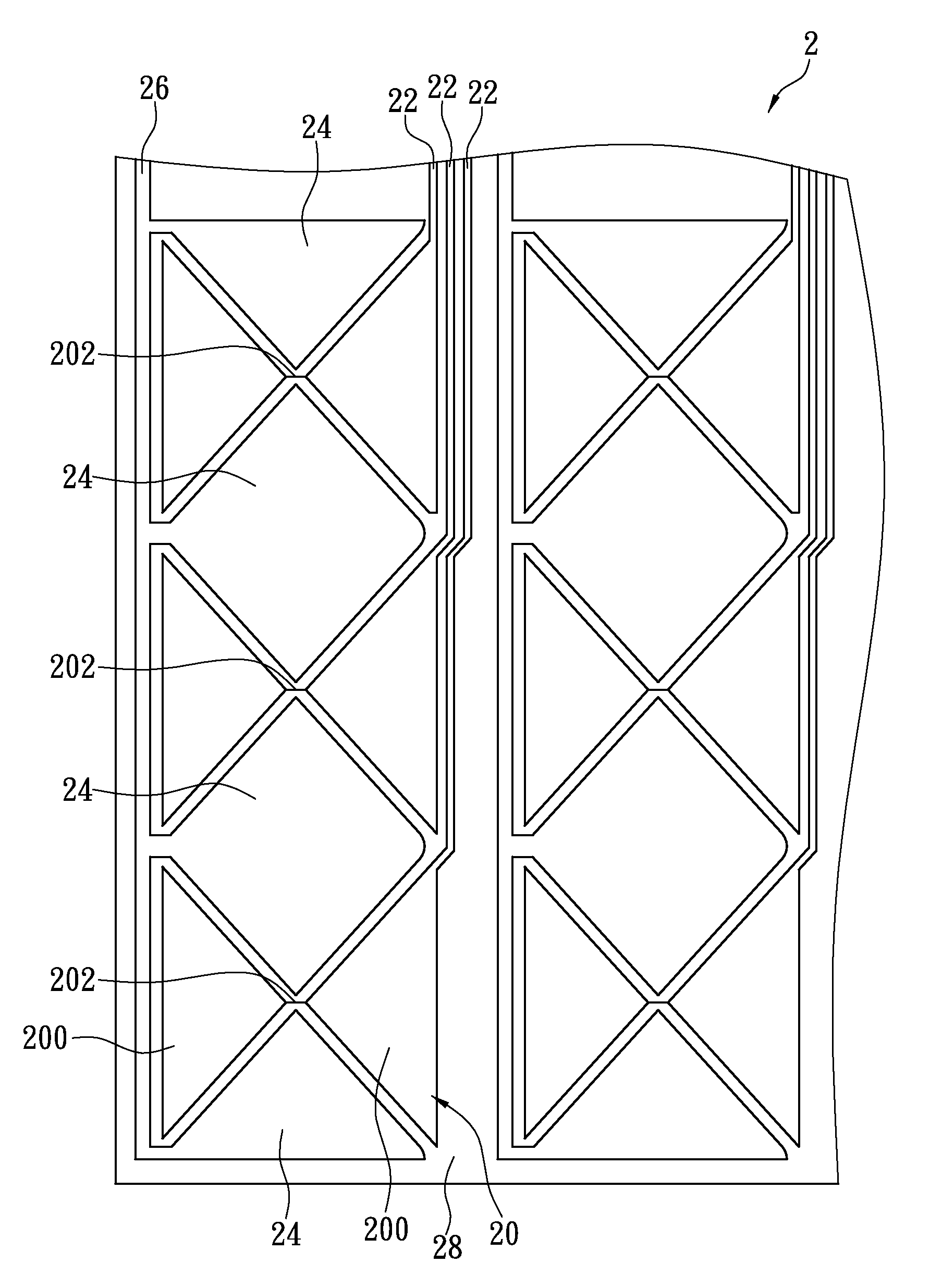
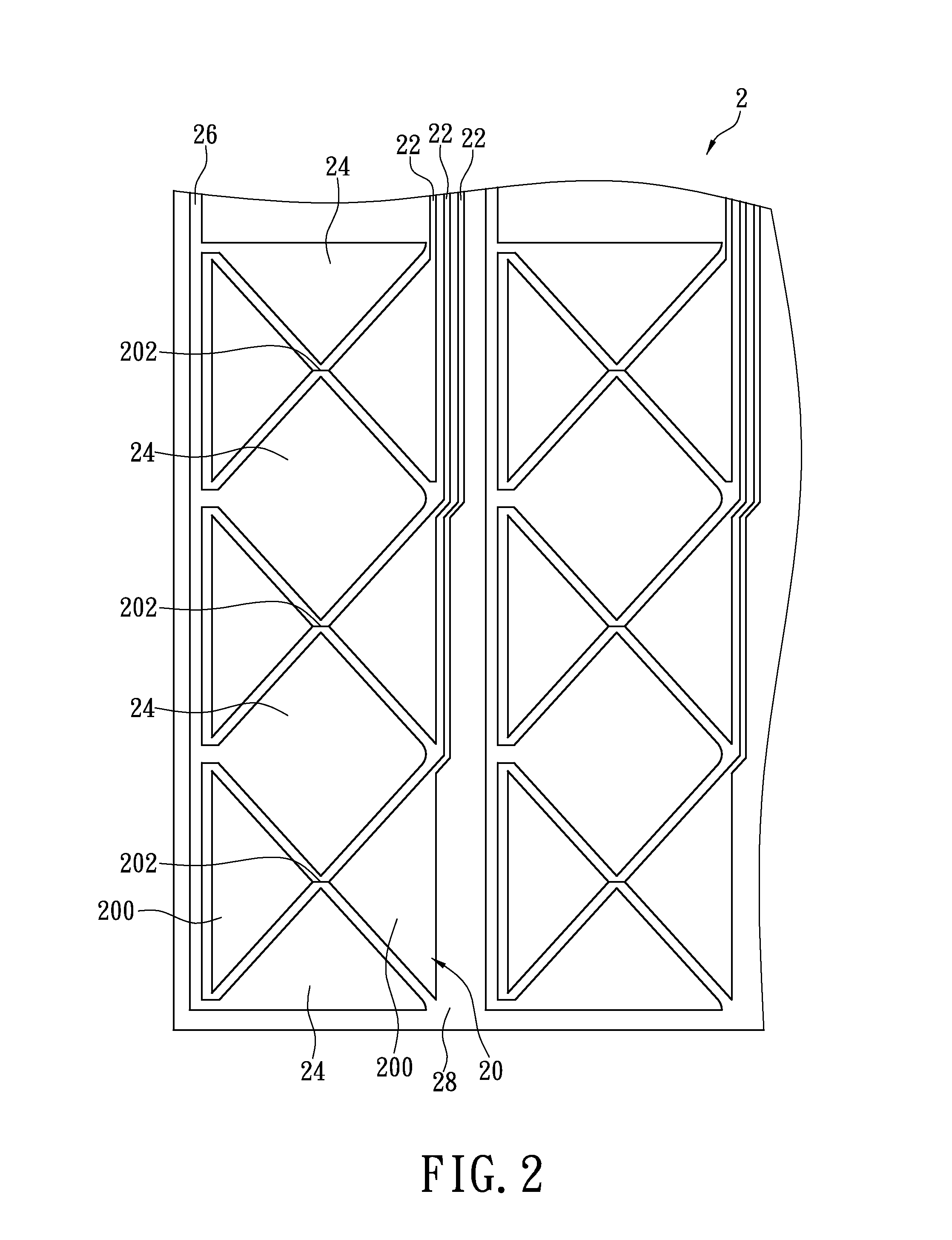
[0013]FIG. 2 shows an embodiment of a capacitive touch control sensor. The capacitive touch control sensor 2 includes a plurality of first electrodes 20, a plurality of first electrode wires 22, a plurality of second electrodes 24 and a plurality of second electrode wires 26. In the instant embodiment, the first and second electrodes 20, 24 and the first and second electrode wires 22, 26 are made of a transparent conductive material selected from a group consisting of: indium tin oxide (ITO), indium zinc oxide, aluminum doped zinc oxide, nanosilver, nanocopper, conductive polymer, carbon nanotube, graphene, silver bromide (AgBr), indium gallium zinc oxide (IGZO) and the combination the...


PUM


Abstract

A capacitive touch control sensor includes a plurality of first electrodes, a plurality of first electrode wires, a plurality of second electrodes, a plurality of second electrode wires. The first and second electrodes are disposed at predetermined interval. The first electrodes have two opposite sensor units and a connecting unit which bridges there-between. Each of the first electrode wires connects one of the first electrodes. Each of the second electrode wires connects more than one of the second electrodes in a same column. The first and second electrodes are arranged alternatively and the neighboring second electrodes are disposed respectively at either side of the connecting unit of the first electrodes.

Description

BACKGROUND[0001]1. Technical Field[0002]The present disclosure relates to a capacitive touch control sensor; in particular, to a single-layered structure.[0003]2. Description of Related Art[0004]FIG. 1 shows an overhead schematic view of a conventional capacitive touch control sensor 1 having a multilayered structure that requires multiple fabrication processes. In a first fabrication process, a plurality rows of first axial electrode blocks 10, a plurality rows of first axial wires 11, and a plurality of rows of separately and adjacently arranged second axial electrode blocks 12 are disposed on a substrate surface of the capacitive touch control sensor 1. The first axial wire 11 interconnects each row of the first axial electrode blocks 10 along a first axial direction, and the second axial electrode blocks 12 are separately interposed between each two adjacent rows of the first axial electrode blocks 10 on either side of the first axial wire 11, respectively. In a subsequent secon...

Claims


Application Information

Patent Timeline
Patent Type & Authority Patents(United States)
IPC IPC(8): H03K17/975
CPCG06F3/044H03K17/9622G06F3/0443G06F3/0446
Inventor YEH, YU-CHOUNI, JUI-MINGLAI, PING-HSUCHEN, TZUNG-HSIEN
Owner J TOUCH CORPORATION
Why Eureka
Try Eureka