Variable phase shifter-attenuator

a phase shifter and variable technology, applied in the field of variable phase shifter attenuators, can solve the problems of not providing variable attenuation, methods that fail to achieve a wide amplitude tuning range, and cannot maintain phase resolution, so as to achieve a large range of variable gain/attenuation

Active Publication Date: 2014-05-13
RAYTHEON CO
View PDF13 Cites 6 Cited by
  • Summary
  • Abstract
  • Description
  • Claims
  • Application Information

AI Technical Summary

Benefits of technology

[0011]With such embodiment, a large range of variable gain / attenuation is achieved without losing phase accuracy. This combines the phase rotator with a coarse attenuator used externally, or by coarsely changing the gain of all states by modifying the current supplied to the circuit digitally. When these external methods are used to provide large (˜10 dB) changes in attenuation, the fine control of the phase rotator is used to provide desired amplitude states at higher amplitude resolution within coarsely-tuned attenuation states.
[0012]The combination of a coarsely-tuned attenuator (or, in one embodiment, bias controller) to the intrinsic fine amplitude control of the phase rotator enables high phase resolution to be maintained over a wide range of attenuator values. Previous methods either fail to achieve a wide amplitude tuning range, or fail to maintain phase resolution as attenuation is increased. Two possible methods to achieve this function are described and include a combination of course and fine attenuation control, such that high phase resolution can be maintained over a wide tunable range of attenuator settings.

Problems solved by technology

In this paper, the phase rotator while proving phase rotation did not provide for variable attenuation.
Previous methods either fail to achieve a wide amplitude tuning range, or fail to maintain phase resolution as attenuation is increased.

Method used


Image

  • Variable phase shifter-attenuator
  • Variable phase shifter-attenuator
  • Variable phase shifter-attenuator

Examples


Embodiment Construction

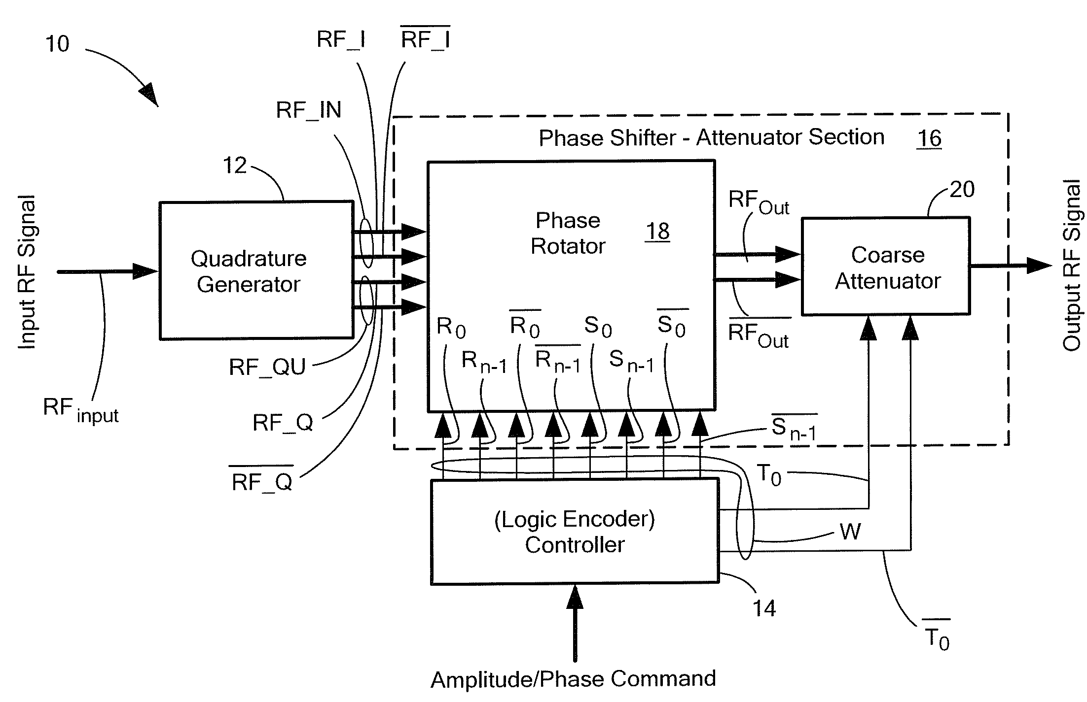
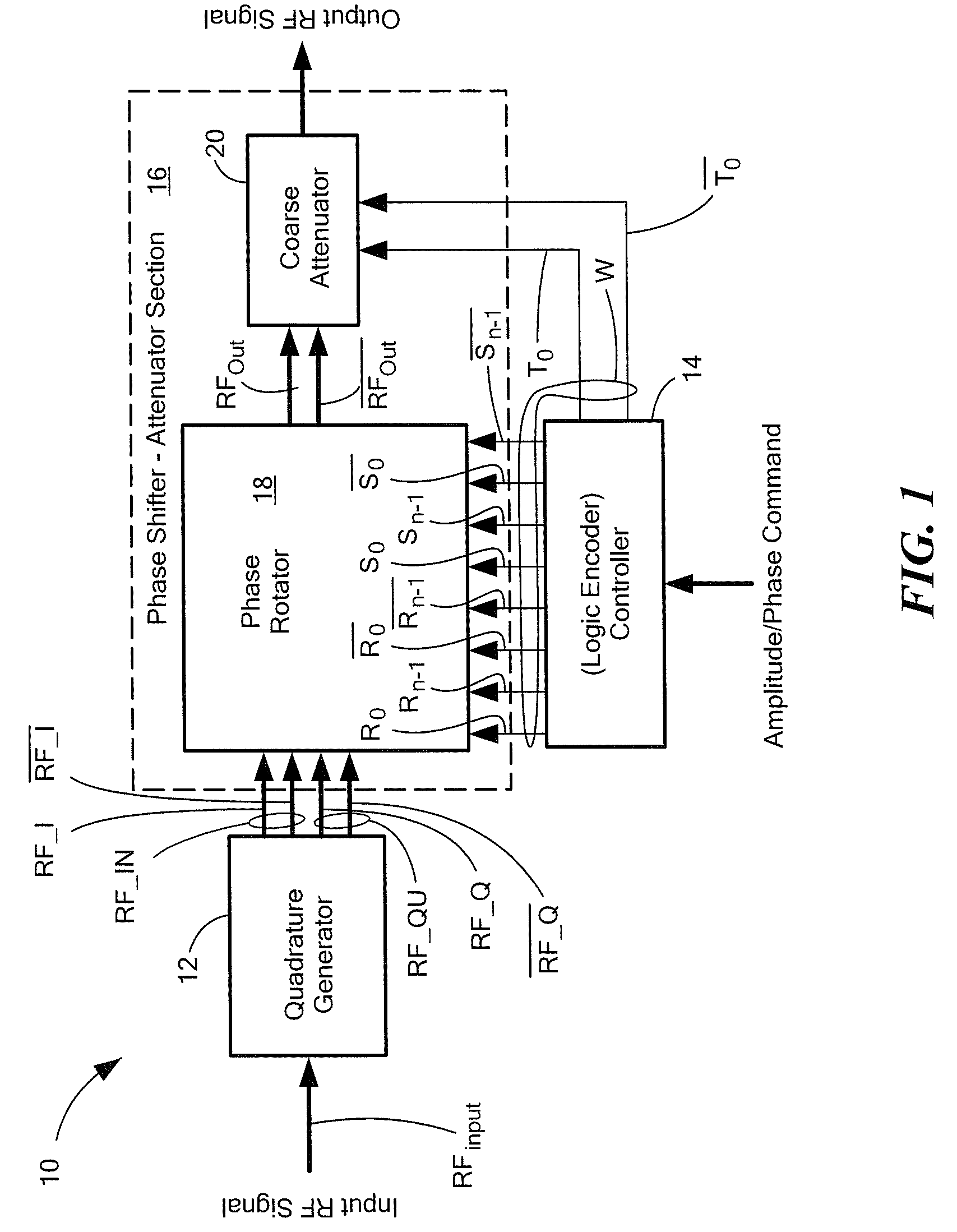
[0027]Referring now to FIG. 1, a phase shifter-attenuator system 10 is shown having: a quadrature section 12 for separating an input signal RFINPUT into a corresponding pair of quadrature channels, one channel (the in-phase channel) having the signal RF_IN, and other channel (the out-of-phase channel, or quadrature channel) having the signal RF_QU with each one pair of quadrature signals having an “true” component and “complement” (or “inverted” component). Thus the in-phase channel RF_IN has true signal FR_I and complement signal, RF_I while the quadrature channel RF_QU has the true signal RF_Q, and the complement signal RF_Q.

[0028]The phase shifter-attenuator system 10 includes a controller 14 for producing a control signal, here a digital word W, representative of a predetermined phase shift and attenuation to be provided to an input signal RFINPUT; and a phase shifter-attenuation section 14. The phase shifter-attenuation section 16 has an in-phase channel fed by the pair of in-p...


PUM


Abstract

A phase shifter-attenuator system having: a controller for producing a digital word representative of a predetermined phase shift and attenuation provided to an input signal; and a phase shifter-attenuation section. The phase shifter-attenuation section includes: a phase rotator for providing one of a plurality combinations of phase shifts-attenuation states to the input signal selectively in accordance with one portion of the produced digital word; and an attenuation section for distributing the plurality of combinations of phase shift-attenuation states over a selected range of attenuations, such range being selected in accordance with a second portion of the produced digital word. The phase shifter-attenuator section provides one of a plurality of combinations of phase shift-attenuation states to the input signal selectively in accordance with one portion of the produced digital word, the combinations being distributed over a range of attentions selected in accordance with a second portion of the digital word.

Description

TECHNICAL FIELD[0001]This disclosure relates generally to variable phase-shifter-attenuators and more particularly to high-resolution digitally controlled variable phase-shifter attenuators.BACKGROUND AND SUMMARY[0002]As is known in the art, variable phase-shifter-attenuators have a wide range of applications. One such application is in phased array antennas where the direction and shape of the antenna beam is formed in accordance with the relative phases and attenuations produced across an array of antenna elements by variable phase-shifter-attenuators in the paths passing radio frequency energy between array of antenna elements and the radar system in accordance with control signals produced by a beam steering computer and fed to the phase-shifter-attenuators.[0003]As is also known in the art, it would be desirable to provide digitally controlled variable phase-shifter-attenuators suitable for fabrication as a monolithic microwave integrated circuit (MMIC). One digitally controlle...

Claims


Application Information

Patent Timeline
Patent Type & Authority Patents(United States)
IPC IPC(8): H04L27/20
CPCH01P1/18H01P1/22H03H7/25H03H11/20H03H11/22H03H11/245H03H11/24
Inventor MORTON, MATTHEW A.COMEAU, JONATHAN P.THOENES, EDWARD W.
Owner RAYTHEON CO
Why Eureka
Try Eureka