Oil separator for internal combustion engine

a technology for oil separators and internal combustion engines, which is applied in the direction of combustion engines, lubrication of crankcase compression engines, pressure lubrication, etc., can solve the problems of difficult to make the trapping performance of oil mist compatible with the pressure loss at sufficient levels, and the pressure loss between the upstream side and downstream sides of the partition wall unavoidably rises according to the decrease in the cross-sectional area of passage holes, so as to improve the trapping performance and efficiency

Inactive Publication Date: 2014-05-20
MAHLE FILTER SYST JAPAN CORP
View PDF18 Cites 13 Cited by
  • Summary
  • Abstract
  • Description
  • Claims
  • Application Information

AI Technical Summary

Benefits of technology

[0005]In order to further improve a trapping performance (efficiency) for oil mist in the inertia collision-type oil separator, it is required to increase the flow velocity of blowby gas ejected from the passage holes by decreasing the cross-sectional area of the passage holes.
[0009]Specifically, with an oil separator provided with a partition wall formed with general passage holes circular in cross-section, under the actions of contraction generated at the inlet opening portion of each passage hole and a boundary layer at the wall surface of each passage hole due to viscosity of fluid, flow of blowby gas concentrates to the cross-sectional center of the passage hole so that blowby gas flows through a cross-sectional central part of the passage hole, thereby narrowing a substantial passage area. This raises a pressure loss across the partition wall at a remarkable high level.
[0010]In contrast, according to the present invention or the oil separator provided with the partition wall formed with the passage holes triangular in cross-section, an area where the flow rate of blowby gas is high can become broader in each passage hole than that in each passage hole circular in cross-section. In other words, a uniform flow velocity distribution of blowby gas can be obtained in each passage hole as compared with the conventional oil separator provided with the partition wall formed with passage holes circular in cross-section. This increases the substantial passage area of each passage hole, thereby lowering a pressure loss across the partition wall. Additionally, according to experiments conducted by the present inventors, as discussed after, the oil separator of the present invention exhibited such results that the pressure loss is lowered while improving the trapping efficiency of oil mist. Although the mechanism for so improving the trapping efficient is strictly unclear, it is assumed that blowby gas containing oil mist flows through each passage hole without being excessively locally concentrated and with a relatively uniform flow velocity distribution to strike against a collision plate, and therefore oil mist can be totally effectively separated.
[0012]Preferably, in the present invention, a plurality of the passage holes are aligned along a direction in which the base of the isosceles triangle extends, in which the respective cross-sectional triangles of the two passage holes adjacent to each other are vertically reversed to each other. With this configuration, the opposite sides of the respective triangles of the two adjacent passage holes are parallel with each other, which is advantageous from the viewpoint of securing a strength of the partition wall. Accordingly, the passage holes can be effectively arranged in a limited region of the partition wall.
[0013]Preferably, in the present invention, each of the passage holes has a length of not less than two times an equivalent diameter of the passage hole. In other words, each passage hole is sufficiently elongate so that flow of blowby gas, particularly oil mist, can certainly strike against the collision plate without excessively spreading.
[0014]Thus, according to the present invention, by forming the passage holes triangular in cross-section, the trapping performance of oil mist and the pressure loss across the oil separator can be compatible at high levels.

Problems solved by technology

However, if the cross-sectional area of each passage hole is thus decreased, a pressure loss between the upstream side and downstream sides of the partition wall unavoidably rises according to decrease in passage hole cross-sectional area.
As a result, this pressure loss lowers the pressure within the oil separator chamber at the downstream side of the partition wall, so that oil tends to reversely flow from the side of the valve operating chamber through the drain pipe to the side of the oil separator chamber, which is problematic.
In other words, it is difficult to make the trapping performance of oil mist compatible with the pressure loss at sufficient levels, the trapping performance and the pressure loss being in the relationship of trade-off in configuration of conventional oil separators.

Method used


Image

  • Oil separator for internal combustion engine
  • Oil separator for internal combustion engine
  • Oil separator for internal combustion engine

Examples


Embodiment Construction

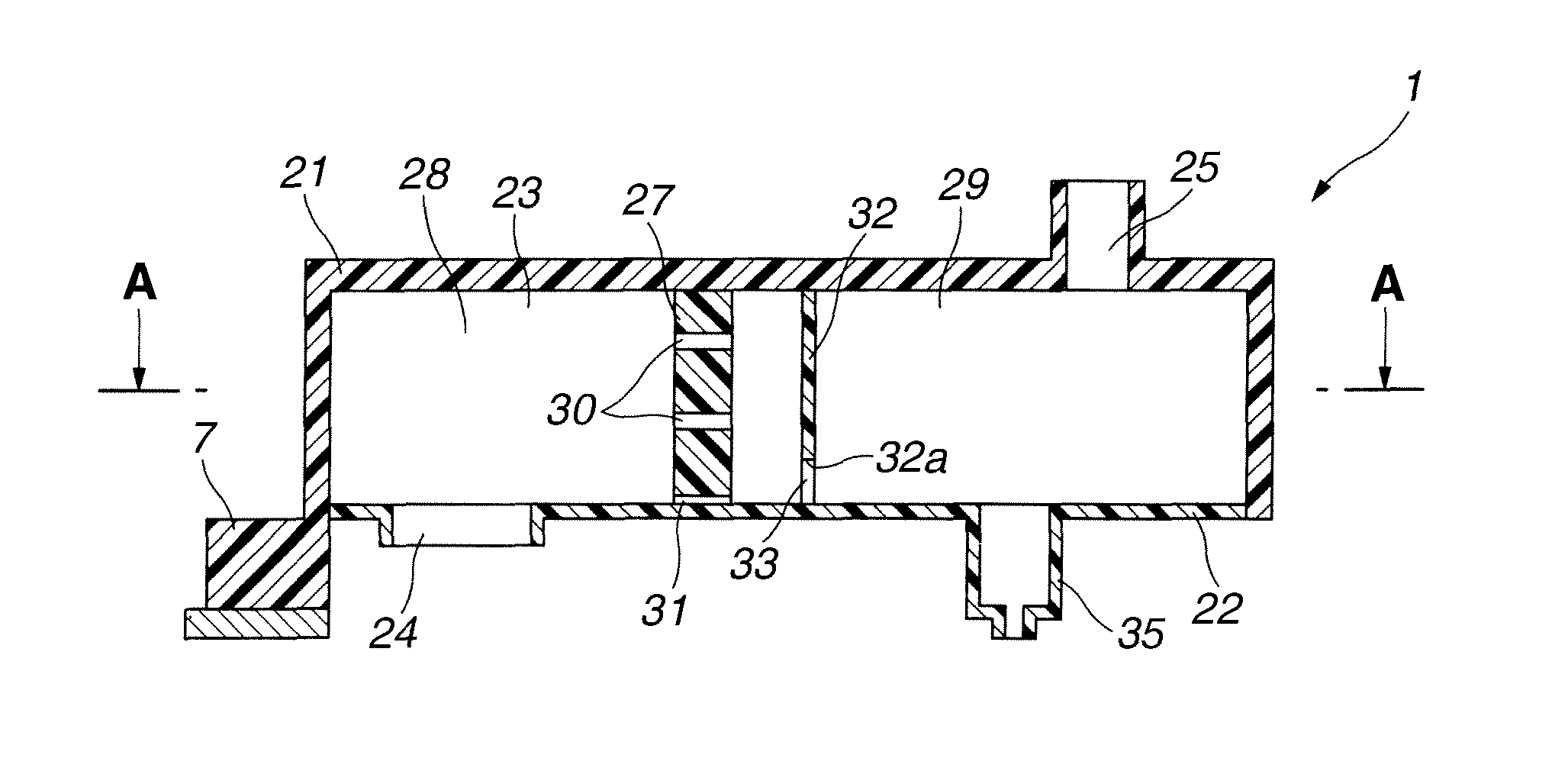
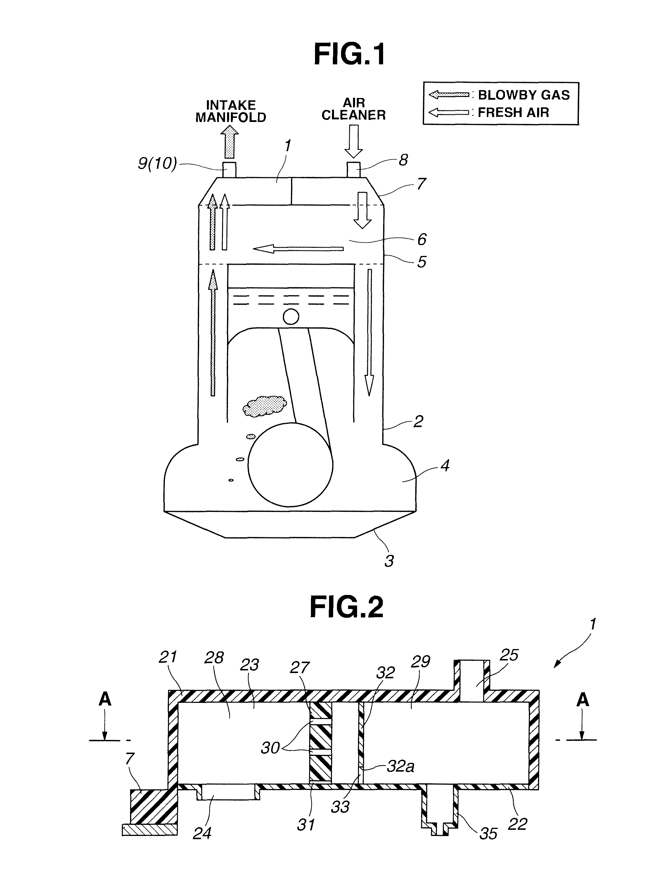
[0031]Referring now to FIG. 1 of the drawings, an embodiment of an oil separator according to the present invention is illustrated by the reference numeral 1. The oil separator 1 is incorporated in an internal combustion engine including a cylinder block 2 and an oil pan 3 which define a crankcase 4. A cylinder head 5 is secured on the cylinder block 2 to form a valve operating chamber 6 thereinside. The valve operating chamber 6 is in communication with the crankcase 4. A cylinder head cover 7 is secured on the cylinder head 5 to form part of a blowby gas treatment system. The cylinder head cover 7 has a fresh air inflow (introduction) opening 8 connected to a part (for example, an air cleaner) of an intake system of the engine which part is located at the upstream side of a throttle valve, though not shown. Additionally, the cylinder head cover 7 has a blowby gas outflow (take-out) opening 9. A known PCV (Positive Crankcase Ventilation) valve 10 is disposed in the blowby gas outfl...


PUM


Abstract

An oil separator disposed inside a cylinder head cover of an internal combustion engine. The oil separator includes a body section defining an elongate separator chamber and having a blowby gas inlet and a blowby gas outlet. A partition wall is disposed to divide the separator chamber into an inlet chamber at side of the blowby gas inlet and an outlet chamber at side of the blowby gas outlet. The partition wall is formed with a plurality of passage holes each of which is triangular in cross-section. A collision plate is disposed inside the outlet chamber and located opposite to the passage holes of the partition wall. A slit-like opening is defined by a lower section of the collision plate and communicated with a drain section for discharging oil separated from blowby gas into a valve operating chamber.

Description

BACKGROUND OF THE INVENTION[0001]This invention relates to improvements in an oil separator disposed inside a cylinder head cover of an internal combustion engine to separate oil mist from blowby gas discharged outside through the cylinder head cover.[0002]For example, in an automotive internal combustion engine, blowby gas containing unburned components and leaked from a combustion chamber to a crankcase is introduced through an engine intake system into the combustion chamber to burn the unburned components together with fresh air taken in from outside, as well known. Blowby gas passing through the inside of the crankcase contains oil mist, and therefore an oil separator is disposed at a part of the cylinder head cover as disclosed in Japanese Patent Provisional Publication Nos. 2005-120855 and 2009-121281 in order to prevent oil mist from being carried to the engine intake system. After oil mist is separated and removed by this oil separator, blowby gas is taken out from the insi...

Claims


Application Information

Patent Timeline
Patent Type & Authority Patents(United States)
IPC IPC(8): F01M13/04
CPCF01M13/0416F01M2013/0433F01M2013/045
Inventor KOBAYASHI, AKIHIRONONAKA, ATSUSHISUTO, MASANORI
Owner MAHLE FILTER SYST JAPAN CORP
Why Eureka
Try Eureka