

Ventilation tubes
- Summary
- Abstract
- Description
- Claims
- Application Information
AI Technical Summary
Benefits of technology
Problems solved by technology
Method used
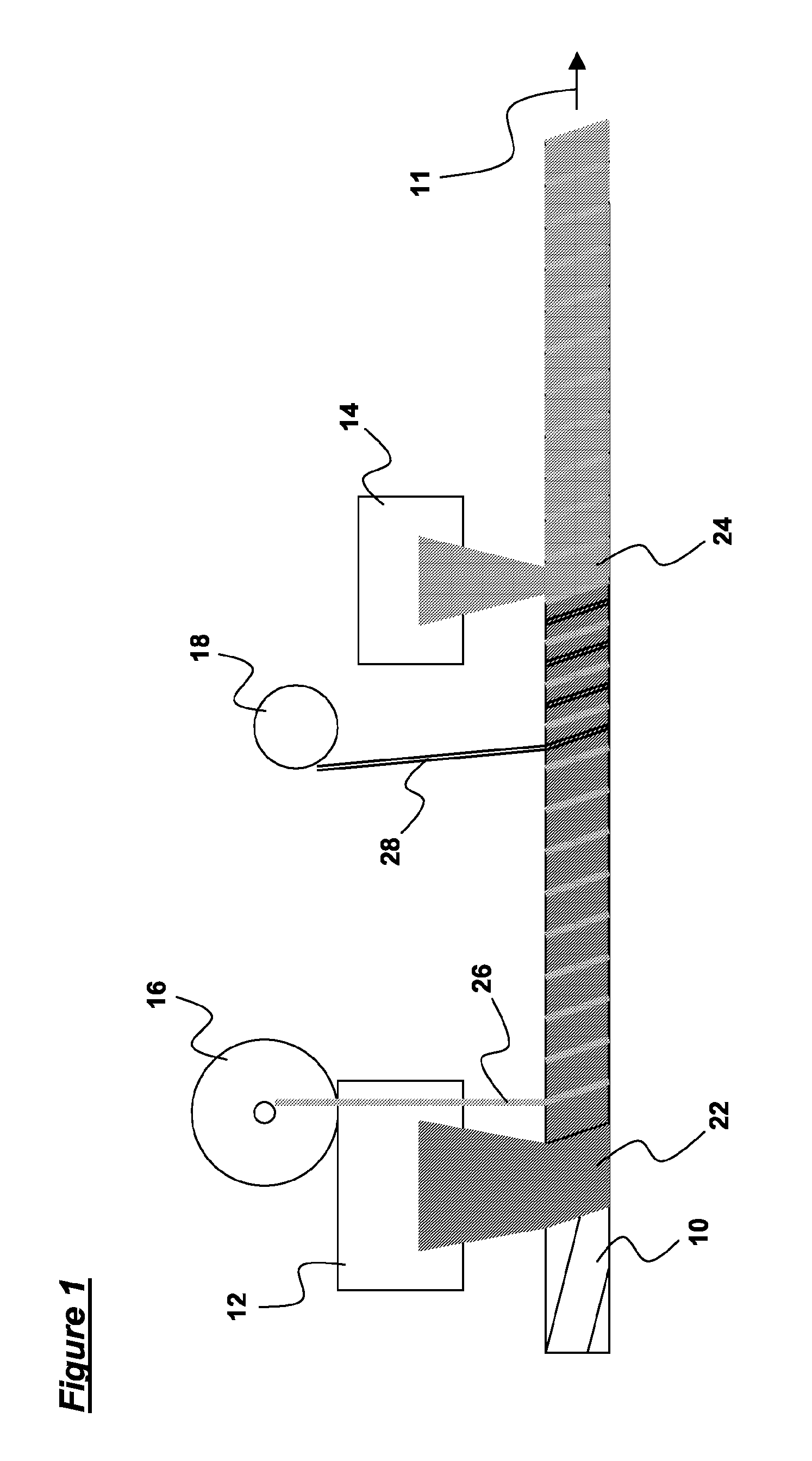
Image

Examples
first embodiment
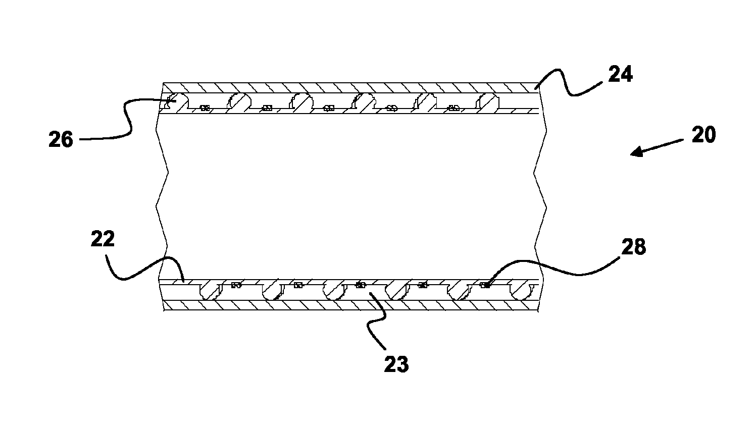
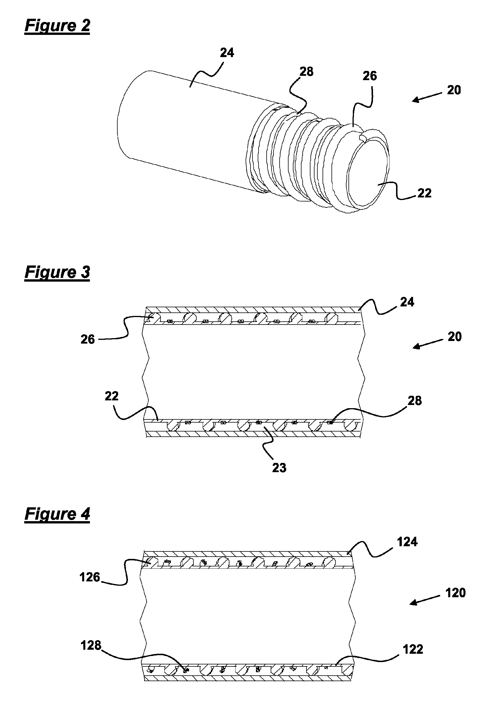
[0053]a ventilation tube according to the invention, manufactured using the method discussed above, is shown in FIGS. 2 and 3, and is generally designated 20. For clarity, only a short length of ventilation tube 20 is shown. In practice, ventilation tubes according to the invention will have a length that will generally be considerably greater than that shown in FIGS. 2 and 3.
[0054]The ventilation tube 20 comprises a generally cylindrical inner wall 22, a generally cylindrical outer wall 24, with a thickness that is greater than that of the inner wall 22, a helical bead 26 that separates the inner and outer walls 22,24, and a heating element 28 bonded to the outer surface of the inner wall 22.
[0055]An insulation chamber 23 is defined between the inner and outer walls 22,24 and the bead 26. The insulation chamber 23 extends helically about the fluid passageway defined by the inner wall 22, along the entire length of the ventilation tube 20. Since the heating element 28 is in contact ...
second embodiment
[0056]a ventilation tube according to the invention is shown in FIG. 4, and is generally designated 120. Again, for clarity, only a short length of ventilation tube 120 is shown. In practice, ventilation tubes according to the invention will have a length that will generally be considerably greater than that shown in FIG. 4.
[0057]This ventilation tube 120 is identical to the ventilation tube 20 of the first embodiment save for the heating element 128 of the second embodiment being only loosely wound about the inner wall 122, rather than being bonded thereto. The method of manufacturing this ventilation tube 120 differs from the method discussed above in that a generally conventional ventilation tube is firstly formed, which comprises the inner wall 122 and bead 126 of the ventilation tube 120 only. The inner wall 122 and bead 126 of the ventilation tube 120 are allowed to cool before the heating element 128 is helically wound about the inner wall 122, and then the outer wall 124 is ...
PUM
| Property | Measurement | Unit |
|---|---|---|
| Temperature | aaaaa | aaaaa |
| Length | aaaaa | aaaaa |
| Thickness | aaaaa | aaaaa |
Abstract
Description
Claims
Application Information