Series bearing support apparatus for a gas turbine engine

a series bearing and gas turbine engine technology, applied in the direction of bearing unit rigid support, machines/engines, liquid fuel engines, etc., can solve the problems of roller bearings that are under-loaded in the radial direction of failure, ball bearings are typically the least reliable bearings in an engine, and ball bearings are more susceptible to failur

Active Publication Date: 2014-05-20
GENERAL ELECTRIC CO
View PDF24 Cites 24 Cited by
  • Summary
  • Abstract
  • Description
  • Claims
  • Application Information

AI Technical Summary

Problems solved by technology

The ball bearings are typically the least reliable bearings in an engine.
Ball bearings are more susceptible for failure when subjected to a combination of axial and radial load, while roller bearings that are under-loaded in the radial direction often fail by roller skidding damage.
Increased radial load on the roller bearings increases cage speed, which decreases the risk of such damage.
Prior art bearing support designs only isolate the majority of radial load.
This design is not completely effective at isolating the radial load from the ball bearings, with typically 10-30% of the applied radial load being transmitted through the ball bearings.
This design is effective at load isolation but is complex to manufacture and operate.

Method used


Image

  • Series bearing support apparatus for a gas turbine engine
  • Series bearing support apparatus for a gas turbine engine
  • Series bearing support apparatus for a gas turbine engine

Examples


Embodiment Construction

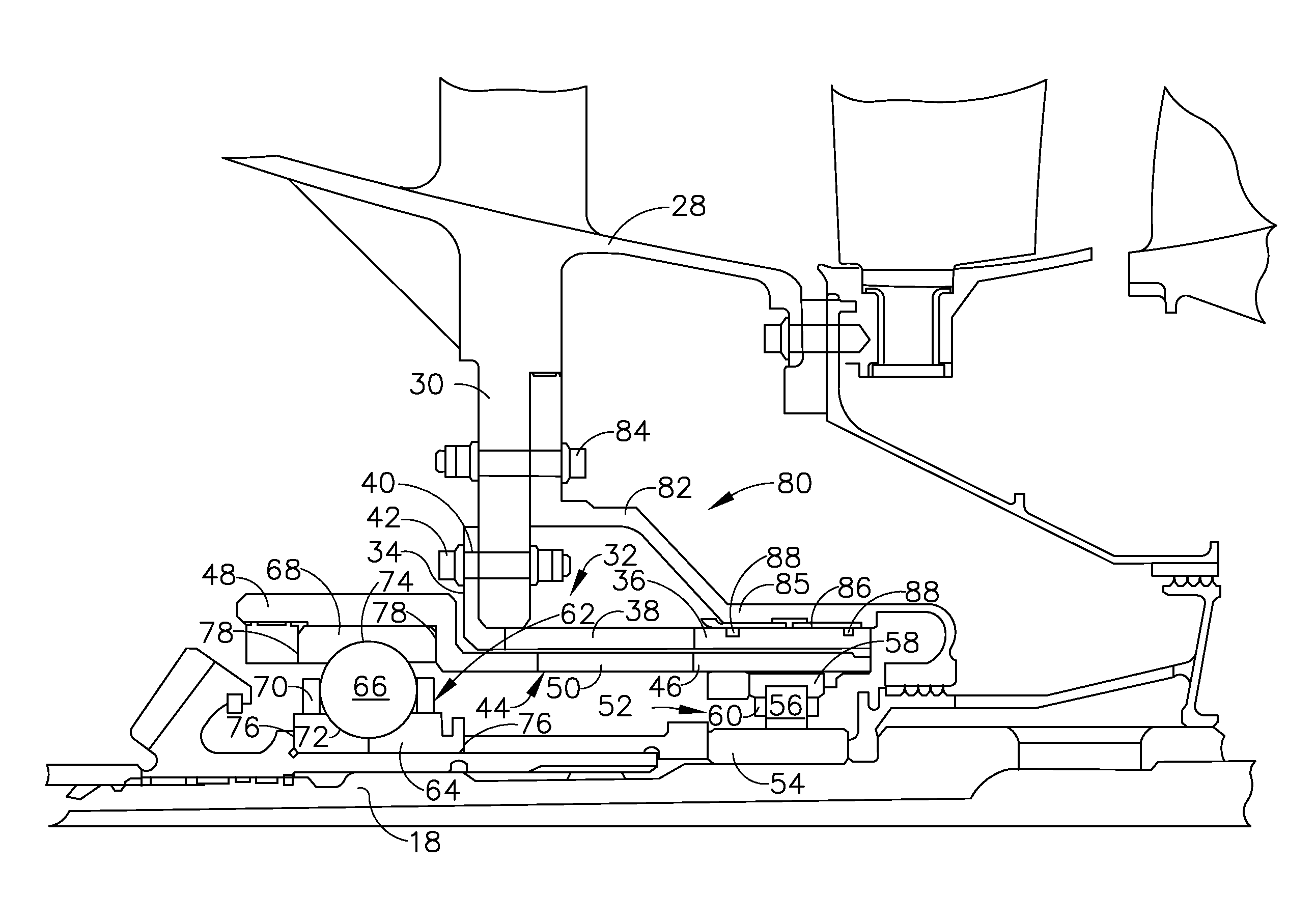
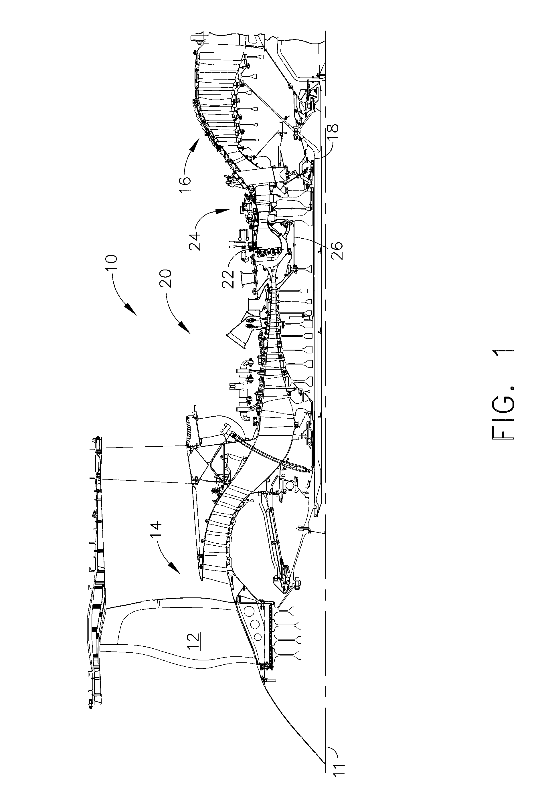
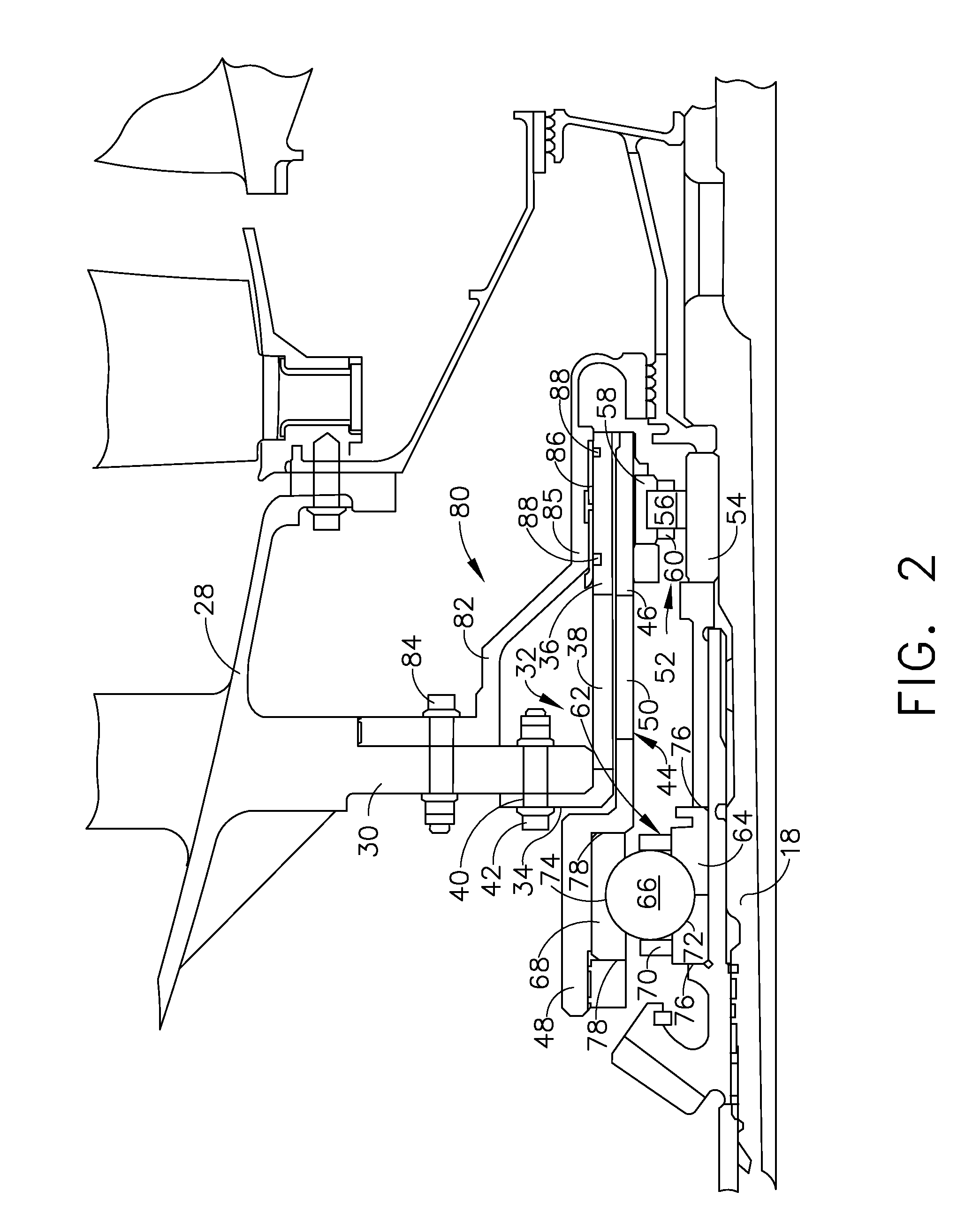
[0016]Referring to the drawings wherein identical reference numerals denote the same elements throughout the various views, FIG. 1 depicts a gas turbine engine 10. The engine 10 has a longitudinal axis 11 and includes a fan 12, a low pressure compressor or “booster”14 and a low pressure turbine (“LPT”) 16 collectively referred to as a “low pressure system”. The LPT 16 drives the fan 12 and booster 14 through an inner shaft 18, also referred to as an “LP shaft”. The engine 10 also includes a high pressure compressor (“HPC”) 20, a combustor 22, and a high pressure turbine (“HPT”) 24, collectively referred to as a “gas generator” or “core”. The HPT 24 drives the HPC 20 through an outer shaft 26, also referred to as an “HP shaft”. Together, the high and low pressure systems are operable in a known manner to generate a primary or core flow as well as a fan flow or bypass flow. While the illustrated engine 10 is a high-bypass turbofan engine, the principles described herein are equally ap...


PUM


Abstract

A bearing support apparatus for a gas turbine engine, including: a first annular member; a second annular member disposed within the first annular member; first and second axially spaced-apart rolling-element bearings disposed between the first and second annular members so as to enable relative rotation of the first and second members; a first spring element mounting the first bearing to the first member; and a second spring element mounting the second bearing to the first member through the first spring element, such that the first and second bearings are physically supported in series relative to the first member.

Description

BACKGROUND OF THE INVENTION[0001]This invention relates generally to rolling element bearings and more particularly to the mounting of such bearings in gas turbine engines.[0002]A gas turbine engine includes one or more shafts which are mounted for rotation in several bearings, usually of the rolling-element type. The bearings are enclosed in enclosures called “sumps” which are pressurized and provided with an oil flow for lubrication and cooling. The bearings in a gas turbine engine are usually a combination of roller and ball bearings. The roller bearings react radial loads of the shafts and the ball bearings react radial and thrust loads. Commonly the bearings are mounted in pairs, with a ball and a roller bearing at axially adjacent positions in a single bearing sump.[0003]The ball bearings are typically the least reliable bearings in an engine. Ball bearings are more susceptible for failure when subjected to a combination of axial and radial load, while roller bearings that are...

Claims


Application Information

Patent Timeline
Patent Type & Authority Patents(United States)
IPC IPC(8): F16C27/00F16C19/49F01D25/16
CPCF16C27/04F01D25/164F16C19/545F16C27/045F16C2360/23F16C19/54
Inventor DO, KEVIN MICHAELSEPPALA, BENJAMIN JOHANNESKERRY, DAVID GARRY
Owner GENERAL ELECTRIC CO
Why Eureka
Try Eureka