Method and apparatus for flue gas treatment

a flue gas treatment and apparatus technology, applied in the direction of hydrogen sulfide, machines/engines, energy input, etc., can solve the problems of difficult modification of existing piping systems, deterioration of net power generation efficiency, and rare use of carbon dioxide separators in gas turbine combined plants. , to achieve the effect of improving the efficiency of carbon dioxide treatmen

Active Publication Date: 2014-05-20
MITSUBISHI HEAVY IND LTD +1
View PDF11 Cites 7 Cited by
  • Summary
  • Abstract
  • Description
  • Claims
  • Application Information

AI Technical Summary

Benefits of technology

[0010]In view of the above, an object of the present invention is to provide a method and an apparatus for flue gas treatment that improve efficiency of treatment of carbon dioxide contained in a flue gas emitted from, for example, a gas turbine.
[0011]As a result of strenuous efforts to solve the problems as described above, the inventors of the present invention have found that, in the recovery of carbon dioxide, it is necessary to generate a high-pressure, high-temperature steam for the recovery and compression of carbon dioxide, and that a boiler which usually uses air for steam generation can use a flue gas from a gas turbine instead of the air for combustion so that the carbon dioxide concentration in the flue gas is increased.

Problems solved by technology

Currently, carbon dioxide separators are rarely used in gas turbine combined plants which are high-efficiency power plants.
When the carbon dioxide separators are employed, however, efficiency of net power generation deteriorates significantly because carbon dioxide concentration in a flue gas emitted from such plants is relatively low and a large amount of power is required for separation (see Japanese Patent Application Laid-Open No. 2000-337108, for example).
However, modification of piping systems of existing facilities is difficult.
Specifically, such modification of specification is difficult to realize in the gas turbine.
Thus, such techniques are not actually adopted.
However, the specification of the gas turbine is determined scrupulously in a design phase, and there is little possibility of actual application of a simple serial installation and sequential use of plural gas turbines for the increase in carbon dioxide concentration.
However, it is difficult to add a large amount of fuel and re-burn.
Thus, conventionally proposed techniques cannot achieve significant improvements in recovery efficiency of the carbon dioxide recovery apparatus.

Method used


Image

  • Method and apparatus for flue gas treatment
  • Method and apparatus for flue gas treatment
  • Method and apparatus for flue gas treatment

Examples


first embodiment

[0039]A flue gas treatment apparatus according to a first embodiment of the present invention will be described with reference to the accompanying drawings.

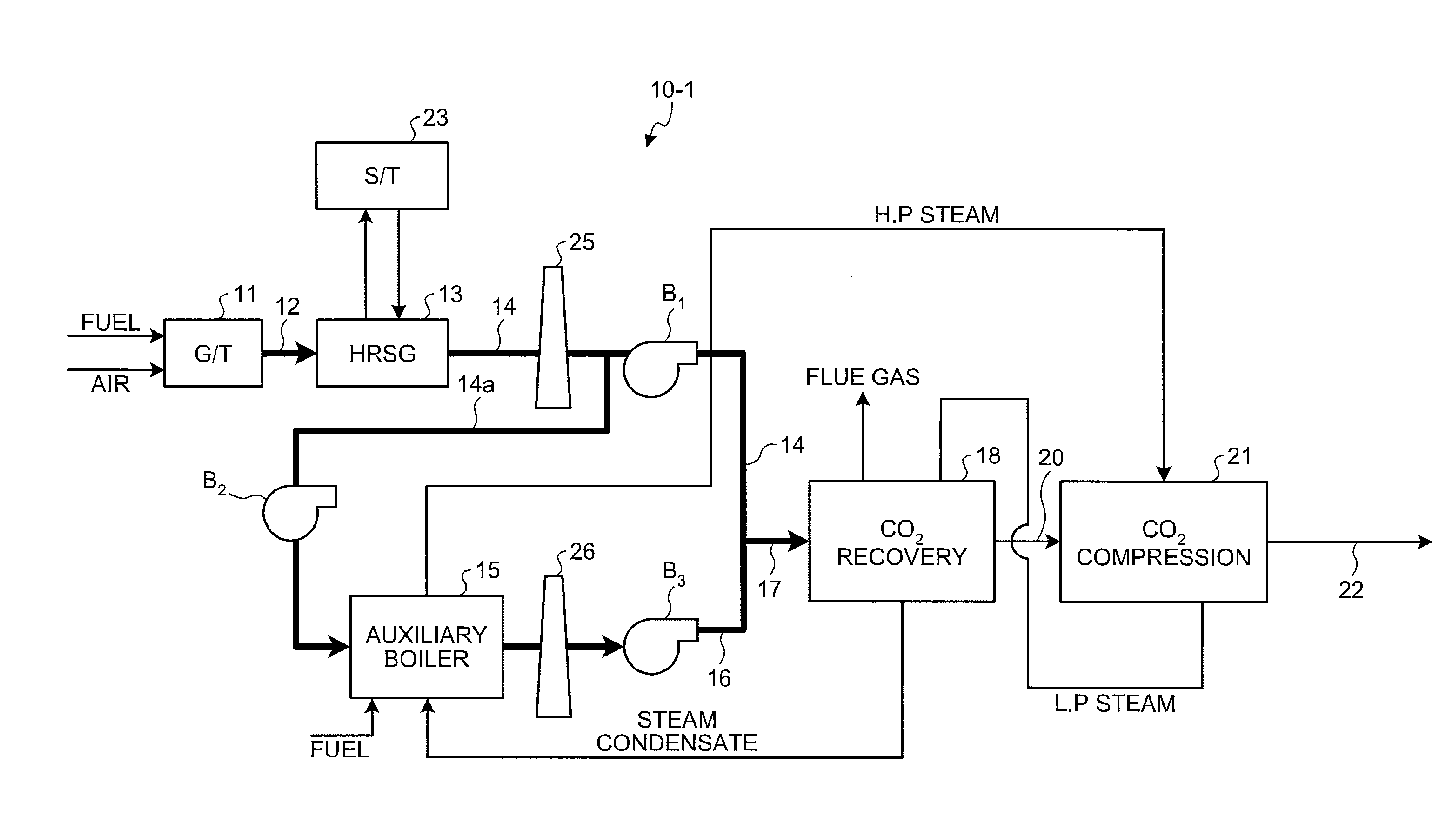
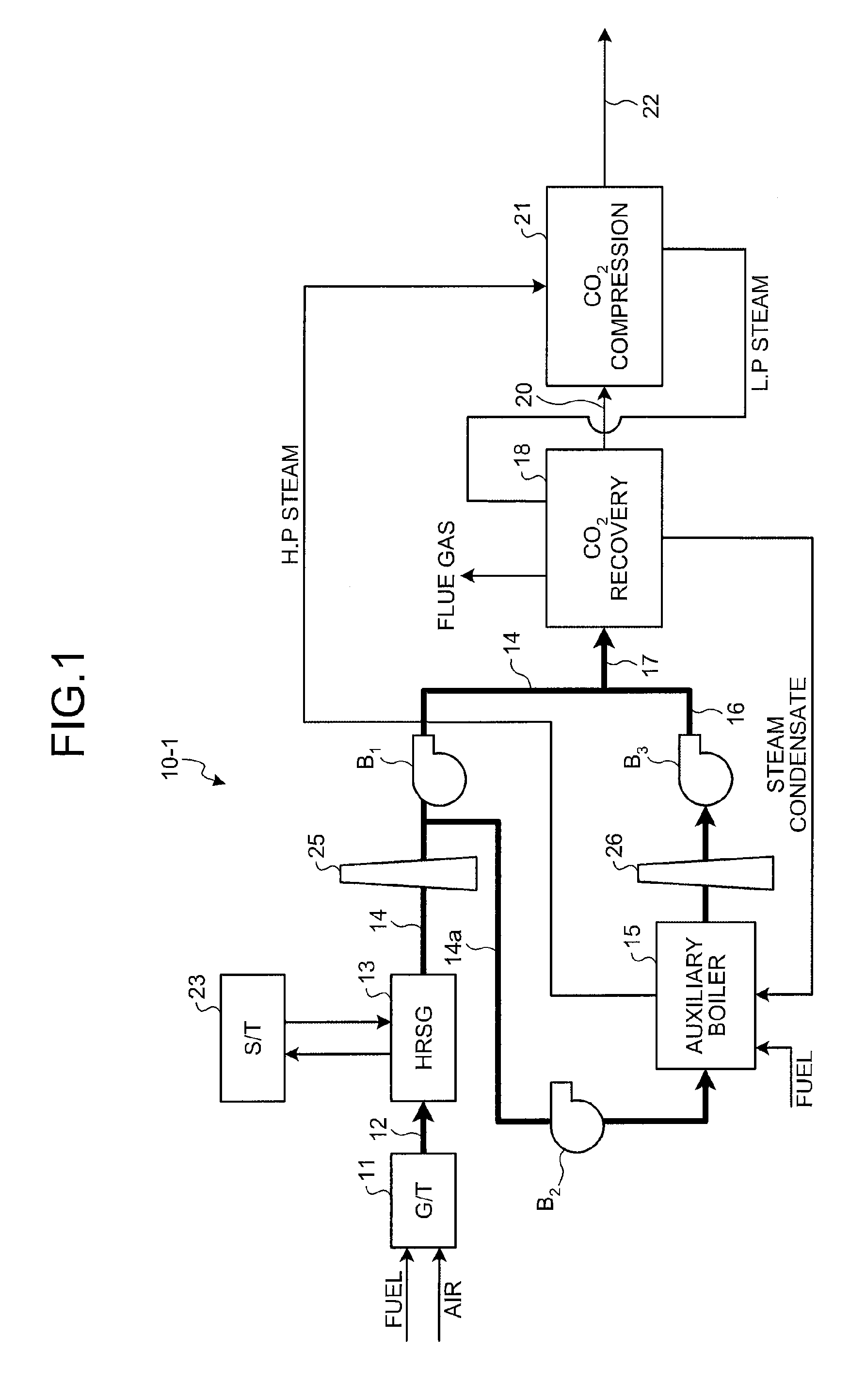
[0040]FIG. 1 is a schematic diagram of the flue gas treatment apparatus according to the first embodiment.

[0041]As shown in FIG. 1, a flue gas treatment apparatus 10-1 of the first embodiment includes a gas turbine (G / T) 11 that is a combustion apparatus causing combustion using, for example, natural gas fuel and air, an exhaust heat recovery boiler (such as HRSG) 13 that recovers high-temperature heat (of approximately 580° C.) of a flue gas 12 emitted from the gas turbine 11, an auxiliary boiler 15 that causes combustion of a branched part 14a (of 10% to 30%) of a flue gas 14 emitted from the exhaust heat recovery boiler 13, and a carbon dioxide recovery apparatus 18 that recovers carbon dioxide in a combined flue gas 17 which includes the flue gas 14 from the exhaust heat recovery boiler 13 and a flue gas 16 from the auxiliary...

second embodiment

[0050]A flue gas treatment apparatus according to a second embodiment of the present invention will be described with reference to the accompanying drawings.

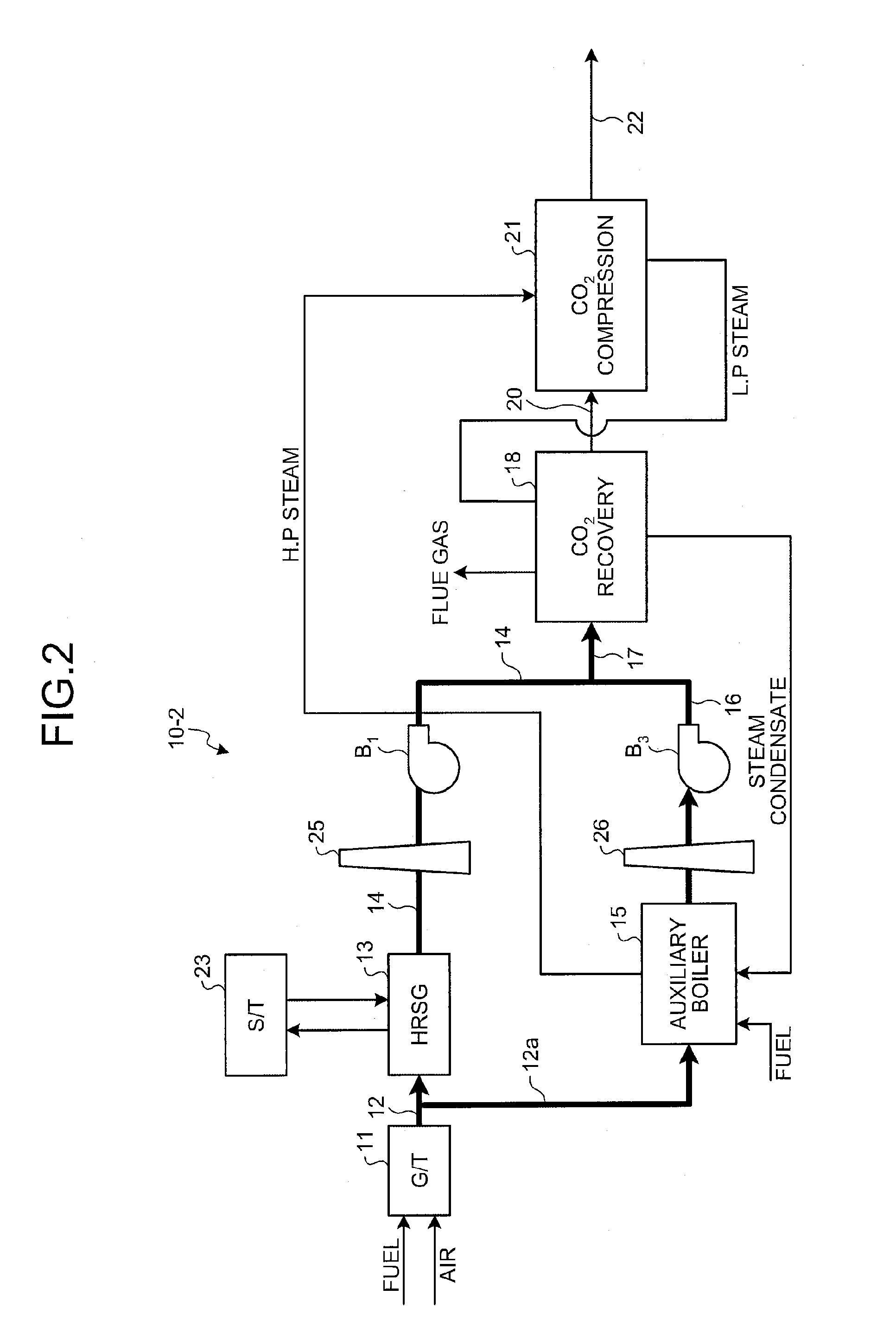
[0051]FIG. 2 is a schematic diagram of the flue gas treatment apparatus according to the second embodiment.

[0052]As shown in FIG. 2, a flue gas treatment apparatus 10-2 of the second embodiment includes a gas turbine (G / T) 11 that is a combustion apparatus causing combustion using, for example, natural gas fuel and air, an exhaust heat recovery boiler (such as HRSG) 13 that recovers high-temperature heat (of approximately 580° C.) of a flue gas 12 emitted from the gas turbine 11, an auxiliary boiler 15 that causes combustion of a branched part 12a of the flue gas 12 emitted from the gas turbine 11, and a carbon dioxide recovery apparatus 18 that recovers carbon dioxide in a combined flue gas 17 which includes a flue gas 16 emitted from the auxiliary boiler 15 and a flue gas 14 emitted from the exhaust heat recovery boiler 13.

[00...

third embodiment

[0056]A flue gas treatment apparatus according to a third embodiment of the present invention will be described with reference to the accompanying drawings.

[0057]FIG. 3 is a schematic diagram of the flue gas treatment apparatus according to the third embodiment.

[0058]As shown in FIG. 3, a flue gas treatment apparatus 10-3 of the third embodiment includes gas turbines (G / T) 11 arranged in parallel as combustion apparatuses causing combustion using, for example, natural gas fuel and air, exhaust heat recovery boilers (such as HRSG) 13 arranged in parallel to recover high-temperature heat (of approximately 580° C.) of flue gases 12 emitted from the gas turbines 11, a carbon dioxide recovery apparatus 18 that recovers carbon dioxide in a flue gas which includes flue gases 14-1 to 14-4 from the plural exhaust heat recovery boilers 13-1 to 13-4, and a boiler 19 that causes combustion of a total amount of the flue gas 12 emitted from at least one gas turbine 11-5 among the plural gas turbi...


PUM

PropertyMeasurementUnit
temperatureaaaaaaaaaa
concentrationaaaaaaaaaa

Abstract

A method for flue gas treatment includes branching part of a flue gas stream emitted from a gas turbine from an upstream side or a downstream side of an exhaust heat recovery boiler and subjecting the branched part to combustion with a fuel in an auxiliary boiler so as to increase carbon dioxide concentration in the branched part prior to recombining the flue gas stream from the auxiliary boiler with the remaining part of the flue gas stream from the gas turbine to form a combined flue gas stream having a carbon dioxide concentration for efficient recovery in a carbon dioxide recovery apparatus.

Description

BACKGROUND OF THE INVENTION[0001]1. Field of the Invention[0002]The present invention relates to a method and an apparatus for flue gas treatment that improve efficiency of treatment of carbon dioxide contained in a flue gas emitted from, for example, a gas turbine.[0003]2. Description of the Related Art[0004]Various techniques have been proposed to separate carbon dioxide from a flue gas generated in power plants thereby to tackle the global warming. Proposed techniques include, for example, Pressure Swing Adsorption (PSA), membrane separation, and chemical absorption. Currently, carbon dioxide separators are rarely used in gas turbine combined plants which are high-efficiency power plants. When the carbon dioxide separators are employed, however, efficiency of net power generation deteriorates significantly because carbon dioxide concentration in a flue gas emitted from such plants is relatively low and a large amount of power is required for separation (see Japanese Patent Applic...

Claims


Application Information

Patent Timeline
Patent Type & Authority Patents(United States)
IPC IPC(8): C01B31/20B01D53/62C01B32/50
CPCY02T10/16F01N5/02F23J2215/50F22B1/1861F01K23/10F22B1/1815Y02E20/32Y02P20/129Y02T10/12
Inventor IIJIMA, MASAKIMUKADAM, HASHAMWEINER, RONALD M.
Owner MITSUBISHI HEAVY IND LTD
Why Eureka
Try Eureka