Controller and control method for a motorised vehicle

a control method and motorised vehicle technology, applied in steering control, digital data processing details, vehicle bodies, etc., can solve the problems of wheelchair toppling, wheelchair toppling, and loss of traction of one wheel, so as to achieve easy configuration and easy control

Inactive Publication Date: 2014-05-20
PENNY & GILES CONTROLS
View PDF16 Cites 1 Cited by
  • Summary
  • Abstract
  • Description
  • Claims
  • Application Information

AI Technical Summary

Benefits of technology

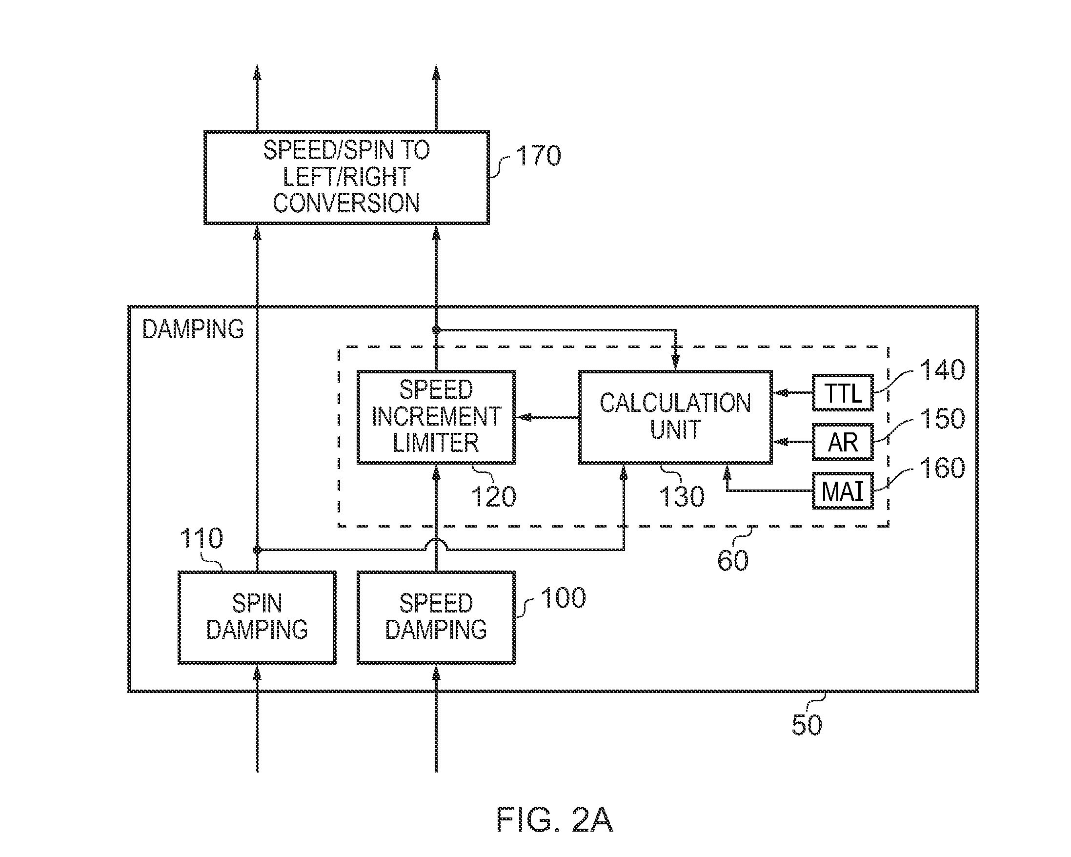
[0013]In accordance with the present invention, the controller is provided with an acceleration control unit which is configured to determine a centripetal force factor corresponding to a centripetal force which is acting on the motorised vehicle as a result of the current control signals being received from the user input device. The centripetal force factor may simply be a calculation of the centripetal force itself, or may be a quantity which is dependent on the centripetal force. Based on the centripetal force factor the acceleration control unit is then configured to calculate an acceleration limit for the motorised vehicle. Significantly, this acceleration limit can be determined such that the motorised vehicle will not lose traction with the surface on which it is driving. The acceleration control unit is then configured to modify the response of the controller to the control signals, such that the motorised vehicle does not exceed the acceleration limit. Hence the acceleration control unit provided in the controller continuously monitors the effect of the control signals being received from the user input device and modifies the response of the controller to the control signals being received from the user input device in order to prevent the motorised vehicle from exceeding the acceleration limit. Since the traction which the motorised vehicle has on the surface on which it is driving reduces as the centripetal force acting on the motorised vehicle increases, the traction of the motorised vehicle may be more reliably maintained by monitoring the centripetal force which is liable to act on the motorised vehicle. Then, in order to keep the wheel torque under a limit at which traction would be lost, the acceleration of the motorised vehicle can be controlled to remain below a calculated limit.
[0030]Viewed from a fifth aspect, the present invention provides a controller for a motorised vehicle arranged to receive control signals from a user input device of the motorised vehicle, the controller configured to control a motor arrangement of the motorised vehicle in dependence on said control signals, the controller comprising: an acceleration control means for determining a centripetal force factor corresponding to a centripetal force which is currently acting on said motorised vehicle as a result of said control signals and for calculating an acceleration limit for said motorised vehicle in dependence on said centripetal force factor, said acceleration control means for applying said acceleration limit by modifying a response of said controller to said control signals, such that said motorised vehicle does not exceed said acceleration limit.

Problems solved by technology

This is done essentially for safety reasons, because for example a maximum spin request (with a left wheel and a right wheel being driven in opposite directions) might be safely requested when the wheelchair is stationary (to thus pivot on the spot), but such a sharp turn could be dangerous if requested when the wheelchair is already travelling with a substantial linear speed.
In a worst case scenario this could cause the wheelchair to topple over.
A loss of traction of one wheel can have undesirable consequences for the handling of the wheelchair when making a turn.
One reason why traction may be lost is the centripetal force acting on the wheelchair during a turn, which will tend to lift the inside wheel thus reducing its traction.
This problem is worse with front wheel drive wheelchairs since the inside wheel is the high torque wheel and is thus more likely to lose traction.
If a significant degree of traction is lost on the inside wheel, then the wheelchair may be liable to spin out of control into the turn.
Even without such drastic lost of control, even a smaller loss of traction may cause handling difficulties for the user of the wheelchair.
Conventional gate shaping approaches to this problem can certainly prevent the wheelchair from overturning, but nevertheless suffer from problems in the handling characteristics of the wheelchair due to the imposed limits on the relative speed and spin affecting the smooth steering feel of the wheelchair, and have led to the overly severe inhibiting of the spin speed in certain joystick demand regions.

Method used


Image

  • Controller and control method for a motorised vehicle
  • Controller and control method for a motorised vehicle
  • Controller and control method for a motorised vehicle

Examples


Embodiment Construction

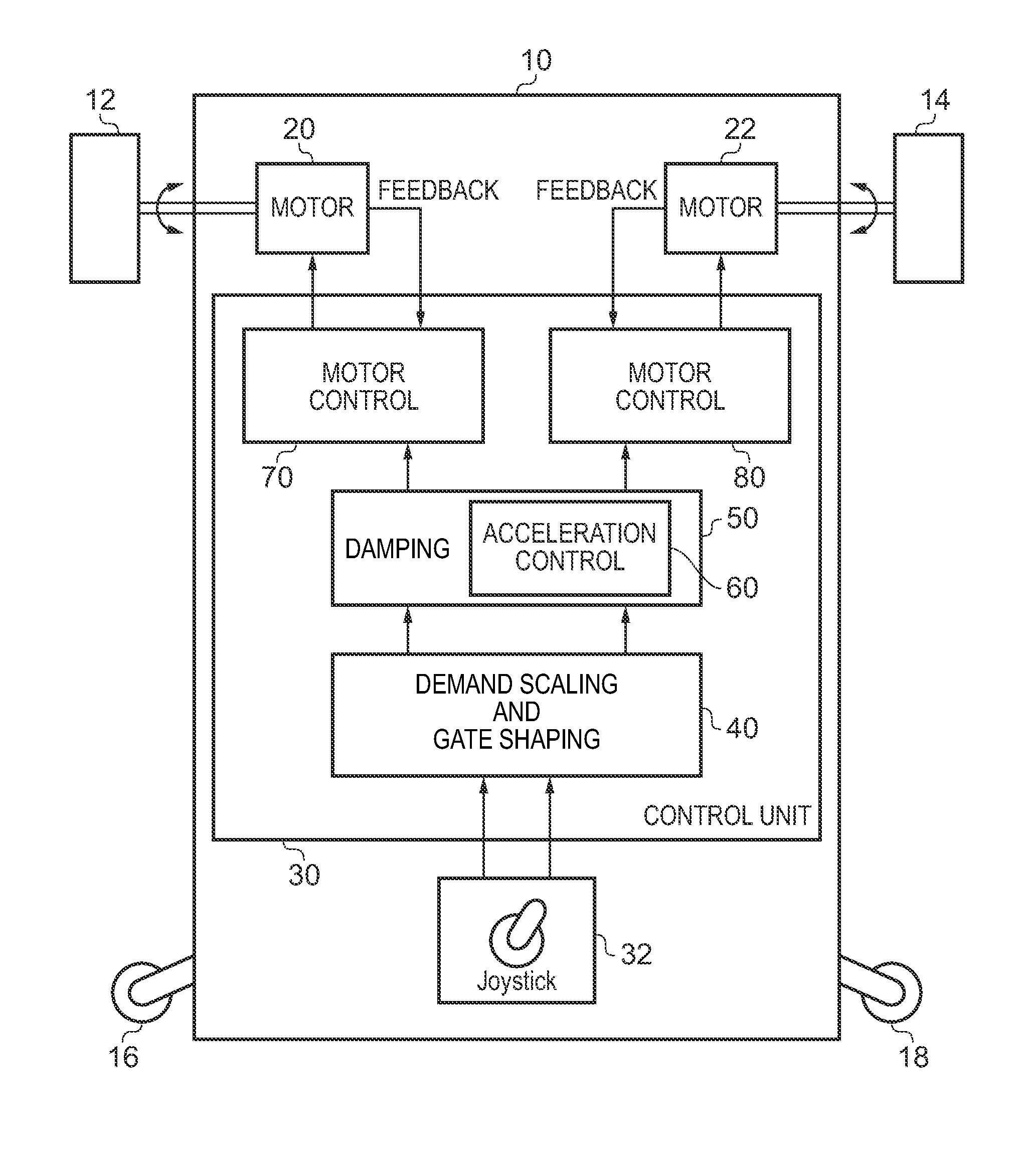
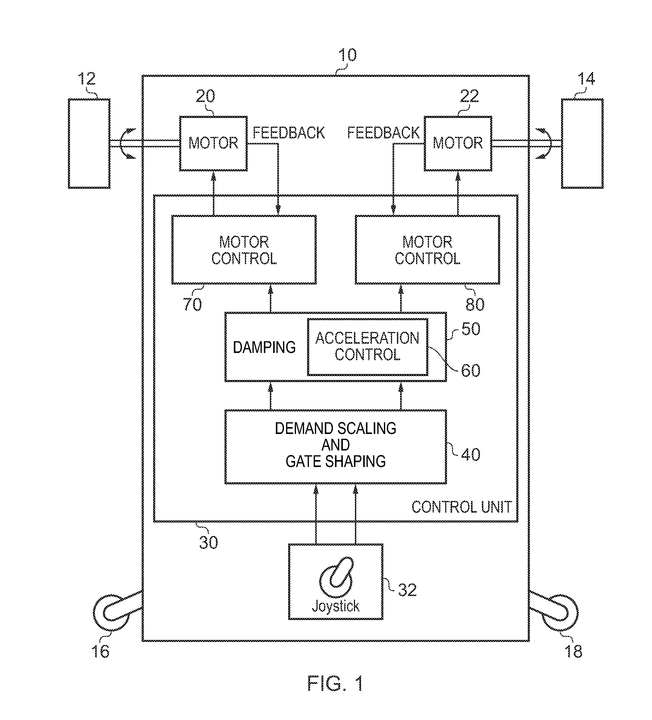
[0039]FIG. 1 is a block diagram of a motorised vehicle in accordance with one embodiment of the present invention. For the purposes of the following discussion, the example where the motorised vehicle is an electric wheelchair will be used. In the example of FIG. 1, the electric wheelchair has a chassis 10 to which two motor driven wheels are connected, namely a left wheel 12 and a right wheel 14. Further, a pair of castors 16, 18 are also provided on the chassis which rotate to follow the direction of the travel of the wheelchair. In the illustrated example, the wheelchair is a front wheel drive wheelchair, so that castors 16, 18 typically follow the direction in which the driven wheels 12, 14 lead (except of course when the wheelchair is in reverse). Each of the two motor driven wheels 12, 14 is driven independently by a motor. In the embodiment illustrated, the left wheel 12 is driven by the motor 20 and the right wheel 14 is driven by the motor 22. To make the electric wheelchai...


PUM

PropertyMeasurementUnit
accelerationaaaaaaaaaa
speedaaaaaaaaaa
velocityaaaaaaaaaa

Abstract

A controller for a motorised vehicle is provided which is arranged to receive control signals from a user input device and the controller is configured to control a motor arrangement of the motorised vehicle in dependence on the control signals. The controller comprises an acceleration control unit configured to determine a centripetal force factor corresponding to a centripetal force which is currently acting on said motorised vehicle as a result of the control signals and is configured to calculate an acceleration limit for the motorised vehicle in dependence on the centripetal force factor. The acceleration control unit is configured to apply the acceleration limit by modifying a response of the controller to the control signals, such that the motorised vehicle does not exceed the acceleration limit.

Description

BACKGROUND OF THE INVENTION[0001]1. Field of the Invention[0002]The present invention relates to a controller and a control method for a motorised vehicle for example an electric wheelchair, wherein the controller receives control signals from a user input device.[0003]2. Description of the Prior Art[0004]Conventional electric wheelchairs have drive wheels which are driven independently by a motor arrangement. Whilst the motor arrangement used to drive the wheels may comprise a single motor with independent couplings between the motor and the wheels to effect independent drive of those wheels, more commonly each driven wheel is driven by an independent motor. Controlling the speed and direction of each driven wheel allows the user to manoeuvre the wheelchair.[0005]A typical input control interface for an electric wheelchair provides a joystick having two control axes, one to control the forward / reverse speed and one to the control the turn rate (or spin). Although such control inter...

Claims


Application Information

Patent Timeline
Patent Type & Authority Patents(United States)
IPC IPC(8): B62D39/00C07C273/16B60L11/00A61G5/04
CPCY02T10/642B60L15/2036B60W2520/125B60W2300/38A61G5/042B60L2200/34A61G2203/14B60L2220/46B60L2240/421B60L2240/16B60W30/18145C07C273/16Y02T10/7275Y02T10/72B60L3/106B60L2240/12B60L2240/20B60L2240/32B60L2240/461B60L2240/465B60L2250/24Y02T10/64B60L15/10
Inventor TROWELL, MATTHEW, JOHN
Owner PENNY & GILES CONTROLS
Why Eureka
Try Eureka