
Mechanical locking system for floor panels

a technology of locking system and floor panel, which is applied in the direction of building components, layered products, walls, etc., can solve the problems of cracks in the floor panel, difficult bending of wood based materials, complicated snap connection, etc., and achieve the effect of improving function and cost, and favorable cost and function

Active Publication Date: 2014-05-27
VÄLINGE INNOVATION AB
View PDF550 Cites 106 Cited by
  • Summary
  • Abstract
  • Description
  • Claims
  • Application Information

AI Technical Summary

Benefits of technology

The present invention is a locking system for floor panels that can be installed in parallel rows, with short edges that can be locked onto long edges using the locking system. This allows for a more cost-effective and efficient locking system compared to existing technologies. The invention also introduces a second horizontal locking system on the long edges, which provides improved function and cost-effectiveness.

Problems solved by technology

Such a snap connection is complicated since a hammer and a tapping block may need to be used to overcome the friction between the long edges and to bend the strip during the snapping action.
Wood based materials are generally difficult to bend.
Cracks in the panel may occur during snapping.
Such projections and recesses are difficult to produce, the panels can only be locked in well defined positions against adjacent long edges and they can not be displaced against each other in angled position against each other when top edges are in contact.
A system with tight fit does not give a safe and reliable locking over time especially if the locking system is made of wood fiber based material, which swells and shrink when the humidity varies over time.
Especially panels with such pretension where the locking strip is bent in locked position and presses the panels together are very difficult to displace and snap.

Method used


Image

  • Mechanical locking system for floor panels
  • Mechanical locking system for floor panels
  • Mechanical locking system for floor panels

Examples


Embodiment Construction

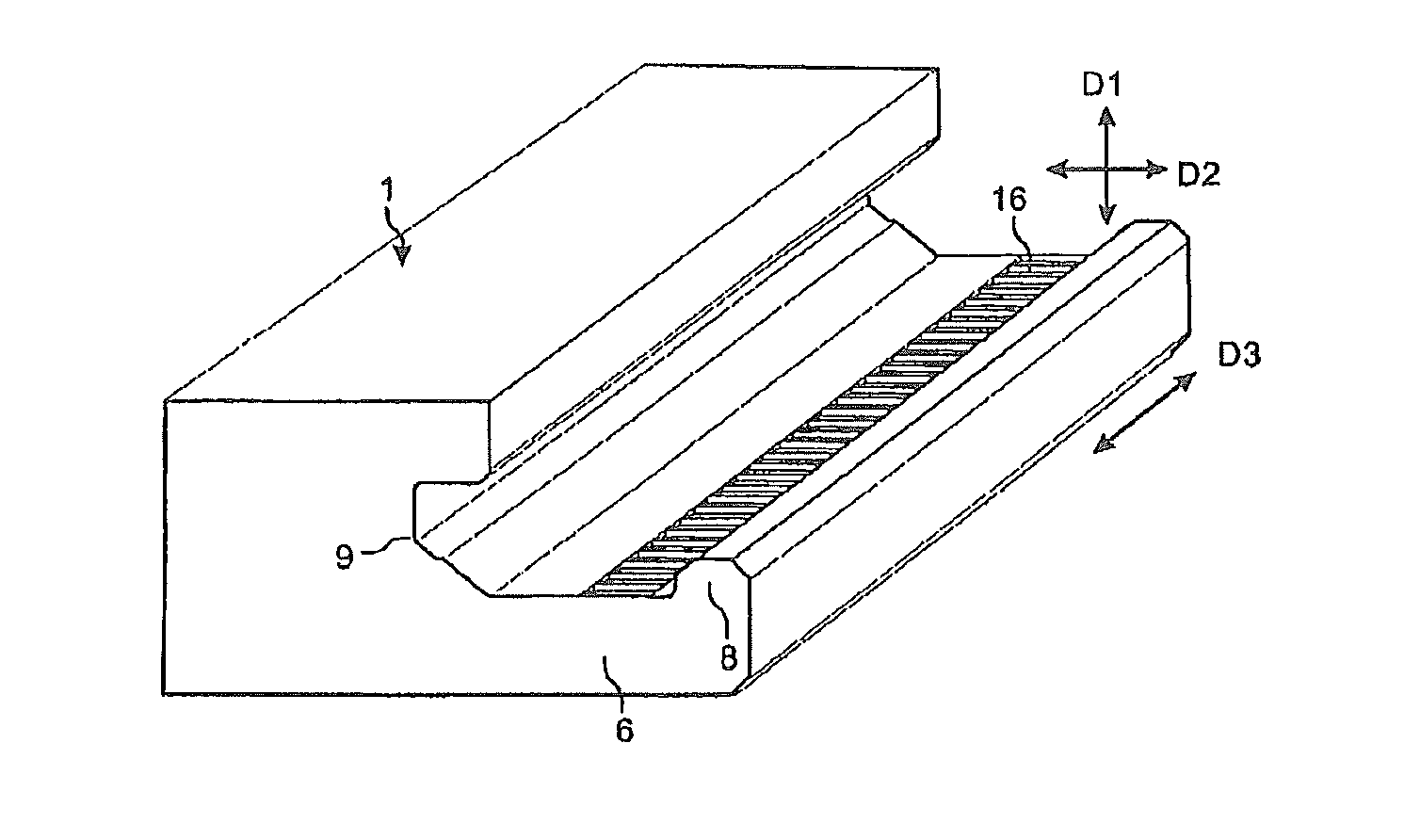
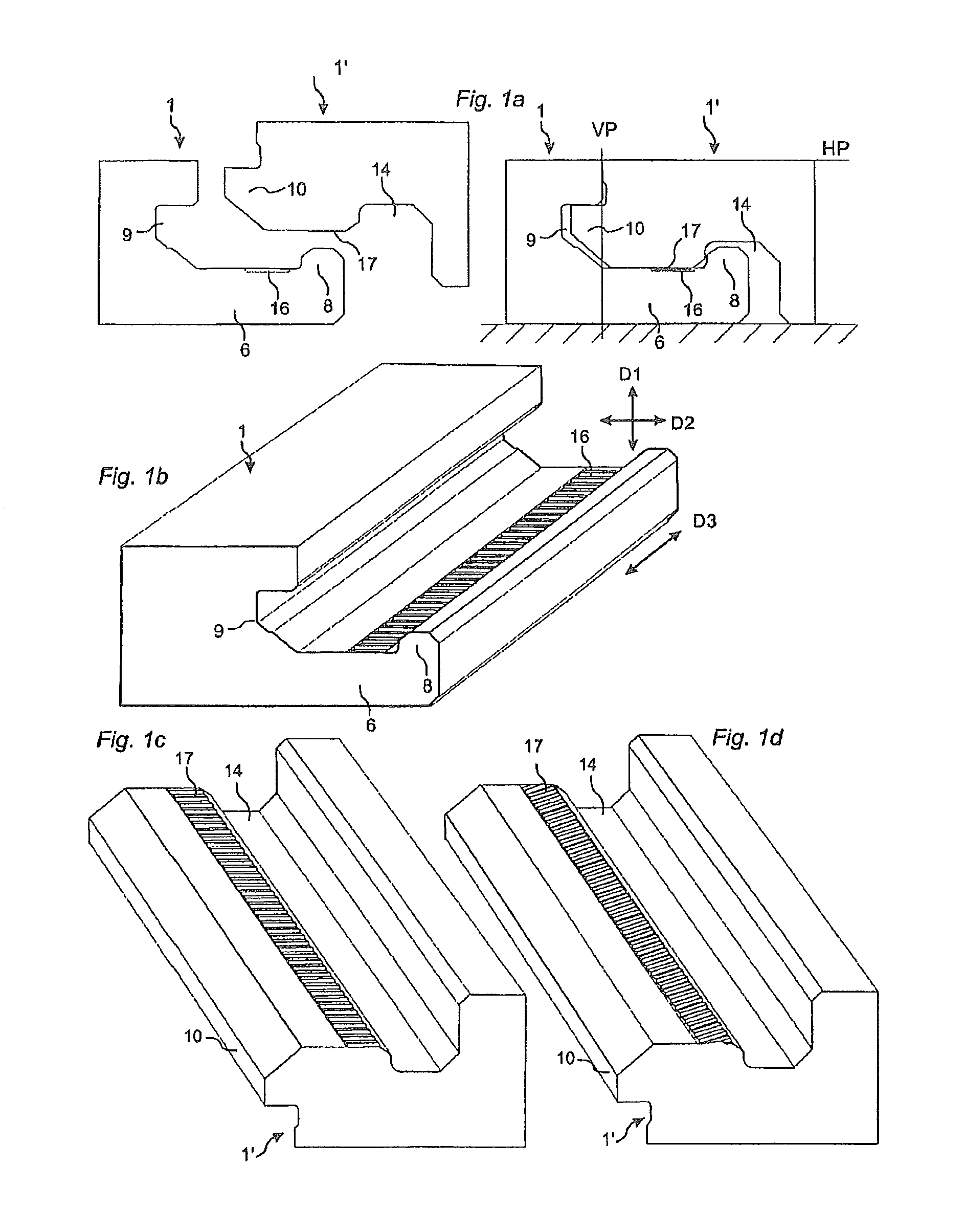
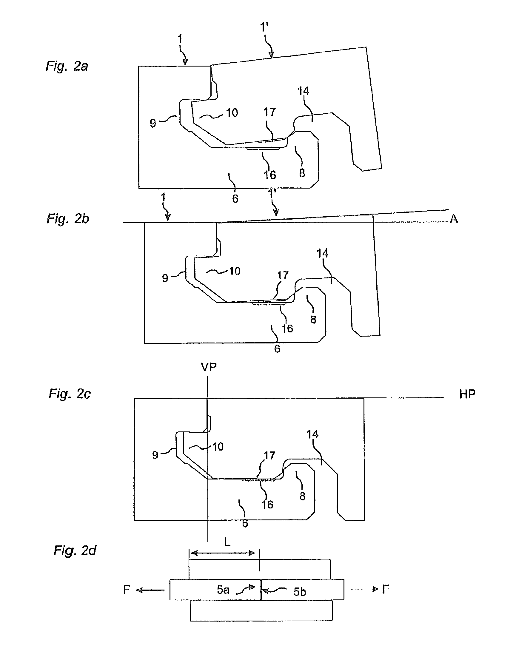
[0043]To facilitate understanding, several locking systems in the figures are shown schematically. It should be emphasized that improved or different functions can be achieved using combinations of the preferred embodiments. The inventor has tested all known and especially all commercially used locking systems on the market in all type of floor panels, especially laminate and wood floorings and the conclusion is that at least all these known locking systems which have one or more locking elements cooperating with locking grooves could be adjusted to a system with a slide lock which prevents displacement along the adjacent edges. The locking systems described by the drawings could all be locked with angling. The principles of the invention could however also be used in snap systems or in systems which are locked with a vertical folding. The slide lock prevents sliding along the joint after snapping or folding.

[0044]The invention does not exclude floor panels with a slide lock on for ...


PUM


Abstract

Floor panels are provided with a mechanical locking system having small local protrusions which reduce displacement along the joint when the panels are laying flat on the sub floor and locked vertically and horizontally.

Description

CROSS REFERENCE TO RELATED APPLICATIONS[0001]The present application is a continuation of U.S. application Ser. No. 11 / 822,684, filed on Jul. 9, 2007, which is a continuation of U.S. application Ser. No. 10 / 908,658, filed on May 20, 2005. The entire contents of each of U.S. application Ser. No. 11 / 822,984 and U.S. application Ser. No. 10 / 908,658 are hereby incorporated herein by reference.TECHNICAL FIELD[0002]The invention generally relates to the field of mechanical locking systems for floor panels and building panels. The invention comprises floorboards, locking systems, installation methods and production methods.FIELD OF APPLICATION[0003]The present invention is particularly suitable for use in floating floors, which are formed of floor panels which are joined mechanically with a locking system integrated with the floor panel, i.e. mounted at the factory, and are made up of one or more upper layers of veneer, decorative laminate or decorative plastic material, an intermediate co...

Claims


Application Information

Patent Timeline
IPC IPC(8): E04F15/02E04F15/04E04B1/10
CPCE04F15/04E04F2201/08E04F2201/0161E04F2201/0153E04F15/02038E04F15/02E04F2201/05E04F2201/023E04F2201/046Y10T428/167
Inventor PERVAN, DARKO
Owner VÄLINGE INNOVATION AB
Features
  • Generate Ideas
  • Intellectual Property
  • Life Sciences
  • Materials
  • Tech Scout
  • Unparalleled Data Quality
  • Higher Quality Content
  • 60% Fewer Hallucinations
Learn More