

Particles
a technology of particles and coil tubing, which is applied in the field of manufactured particles, can solve the problems of affecting the flow, affecting the effect of treatment, etc., and achieves the effects of increasing the capacity, increasing the production, and constant wall thickness
Active Publication Date: 2014-05-27
ROBERTSON EWEN
View PDF14 Cites 1 Cited by
- Summary
- Abstract
- Description
- Claims
- Application Information
AI Technical Summary
Benefits of technology
The patent describes a new type of particle used in oil wells that has a curved surface. This design improves the flow of oil and gas from the well, and also helps to keep the pressure drop down. The particles can be made in a variety of shapes, such as spherical or egg-shaped. The patent also suggests that by placing the particles and chemical additives in direct contact with the filter cake, the contact area between them can be maximized, which can lead to better results in the well.
Problems solved by technology
Sand production from hydrocarbon producing wells is a common problem which can inhibit the flow of hydrocarbons and damage the well.
However a problem with such a delivery is that the chemicals will tend to act on the thinnest section of filter cake.
In the presence of a gravel pack, application of chemicals using coil tubing strings to place the treatment in-situ to act on, for example, a filter cake, is particularly ineffective because it is often difficult for the chemicals to be directed at the filter cake due to much of the space being taken by the gravel pack.
Method used
View moreImage
Smart ImageViewing Examples

Examples
second embodiment
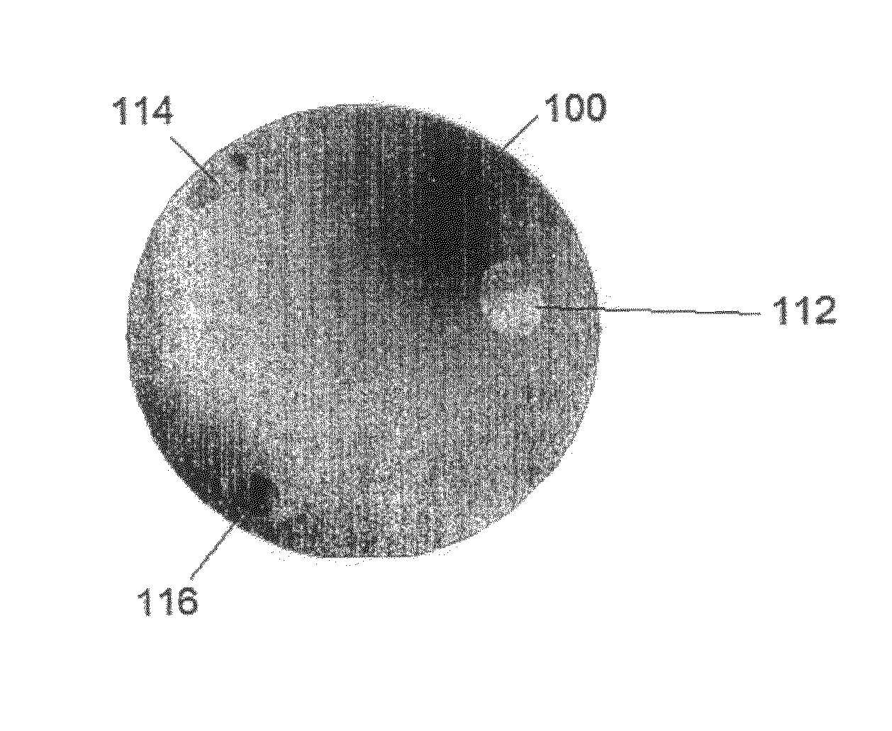
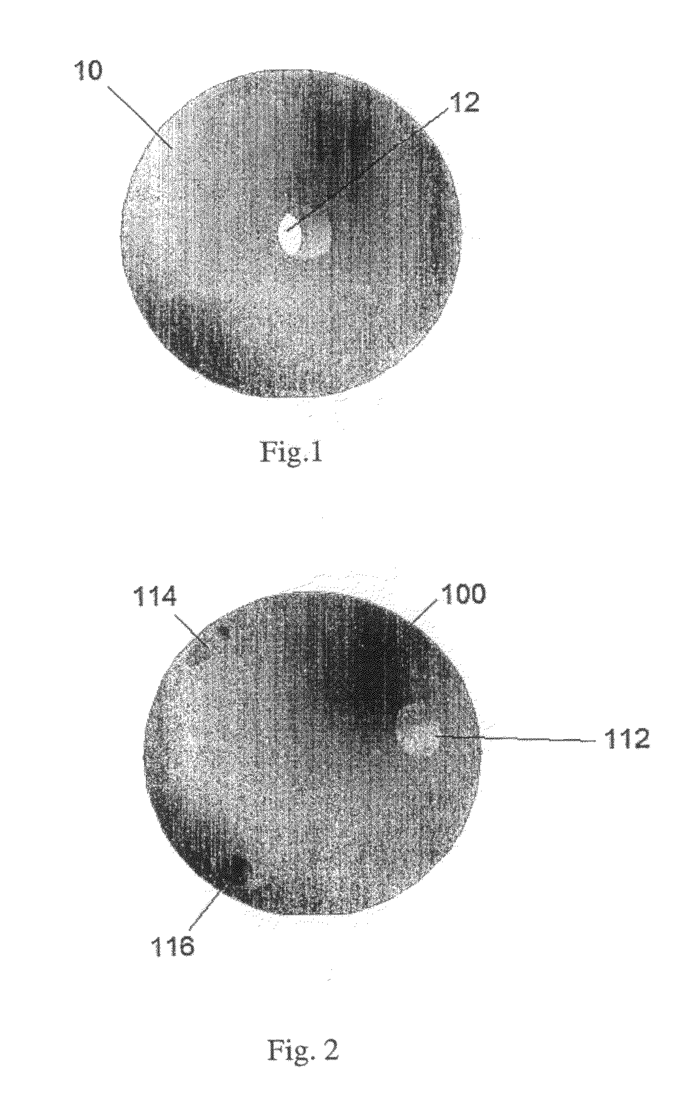
[0092]a particle 100 is shown in FIG. 2. The particle in FIG. 2 is the same as the particle in FIG. 1 except that it includes further ports 114, 116 which are at right angles to a first port 112.
first embodiment
[0093]The flow rate through a gravel pack comprising particles such as particle 100 is even higher than that of the invention.
third embodiment
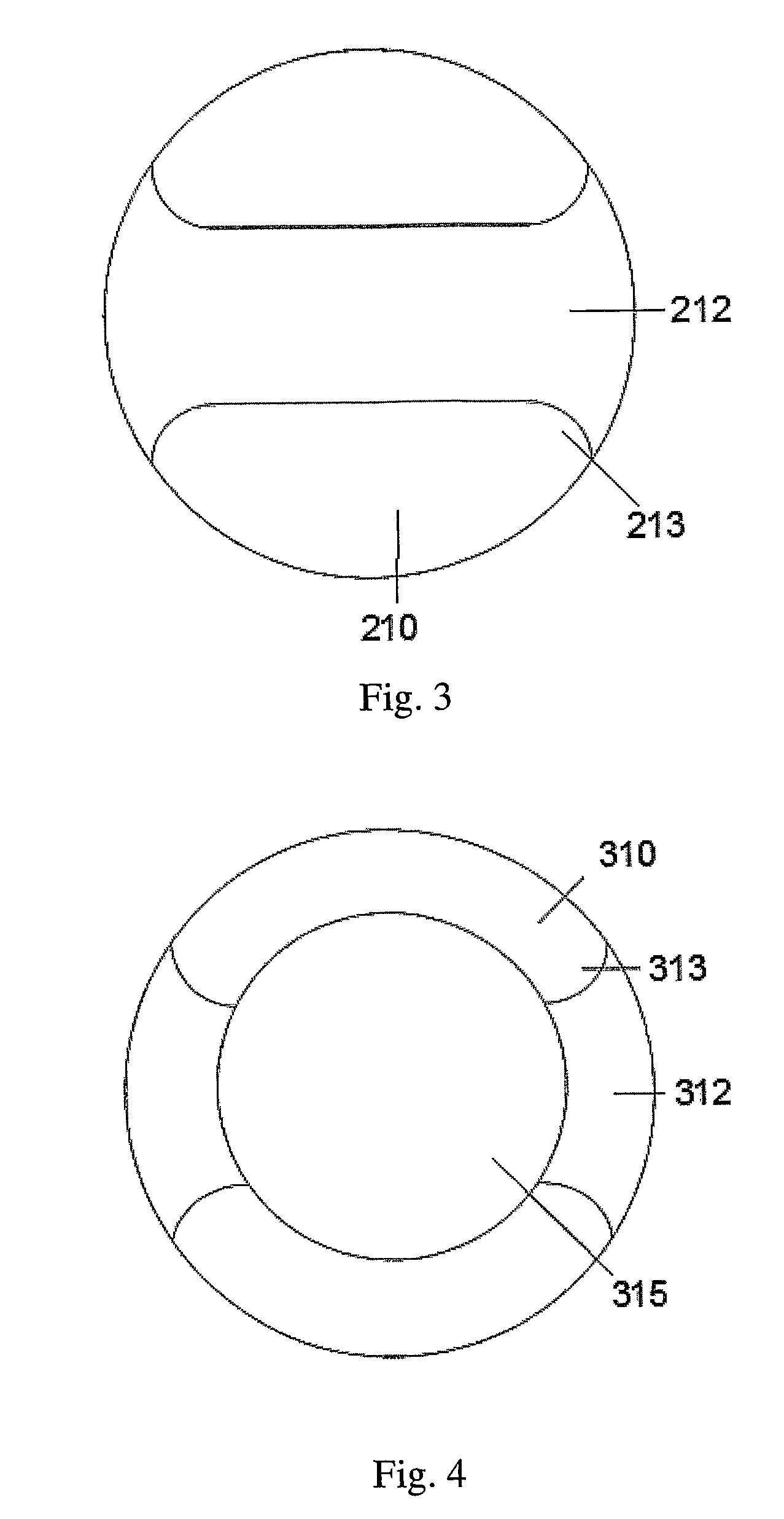
[0094]a particle 210 is shown in FIG. 3. The particle is similar to that of FIG. 1, but it has a radiused edge 213 where the port 212 meets the surface outer surface of the particle 210.
Login to View More PUM
| Property | Measurement | Unit |
|---|---|---|
| specific gravity | aaaaa | aaaaa |
| thickness | aaaaa | aaaaa |
| diameter | aaaaa | aaaaa |
Abstract
Manufactures particles comprising a chemical treatment agent which are useful in wells are provided. The particles have the advantage of being able to chemically treat a well, e.g. to remove filter cake. Embodiments of the invention improve well production by providing sand control and / or increasing permeability of a gravel pack. Methods of using the particles and a gravel pack comprising the particles are also provided.
Description
FIELD OF THE INVENTION[0001]This invention relates to a manufactured particles and method for it's use in wells, particularly but not exclusively for sand control and / or delivery of chemicals in hydrocarbon production wells.BACKGROUND[0002]Sand production from hydrocarbon producing wells is a common problem which can inhibit the flow of hydrocarbons and damage the well. To mitigate this problem, a sand screen may be deployed in the well which acts as a filter to resist ingress of particles above a certain diameter.[0003]In order to protect the sand screen from hole collapse, in-situ geo-mechanical loads and stresses and in order to enhance its filtering function, it is known to add a “gravel pack” external to the screens to support the open hole formation rock structure in the well. A gravel pack is a plurality of gravel particles, which allow the flow of fluid therebetween but resist the flow of sand therebetween.[0004]The delivery of chemical treatment agents is often done using c...
Claims
Login to View More Application Information
Patent Timeline
 Patent Type & AuthorityPatents(United States)
IPC IPC(8): C09K8/80
CPCE21B43/25C09K8/536
InventorROBERTSON, EWEN
OwnerROBERTSON EWEN