
Method for diagnosing a sensor unit of an internal combustion engine

a sensor unit and internal combustion engine technology, applied in the direction of machines/engines, electric control, instruments, etc., can solve the problems of increasing the weight of a motor vehicle, increasing the number of sensors, and requiring considerable spa

Inactive Publication Date: 2014-06-03
ROBERT BOSCH GMBH
View PDF8 Cites 2 Cited by
  • Summary
  • Abstract
  • Description
  • Claims
  • Application Information

AI Technical Summary

Benefits of technology

The present invention aims to improve a method for detecting errors in a sensor unit used in an internal combustion engine. The invention allows for reliable detection of various error patterns with minimal limitations. Additionally, the invention allows for the dispensing of a redundant design of the sensor units. The invention also provides a reference frequency that can be related to the crankshaft or camshaft of the engine, which simplifies the evaluation of changes in the output signal of the sensor unit over time. This reference frequency helps with accurately interpreting the phase characteristics of these changes.

Problems solved by technology

However, this is expensive, requires considerable space, and increases the weight of a motor vehicle.
In addition, the increase in the number of sensors is accompanied by an increased probability of failure of the overall system.
This type of error detection may be easily carried out, but has the disadvantage of a time-limited monitoring range.
In addition, it is not always possible to unambiguously identify a defective sensor of a sensor system.

Method used


Image

  • Method for diagnosing a sensor unit of an internal combustion engine
  • Method for diagnosing a sensor unit of an internal combustion engine
  • Method for diagnosing a sensor unit of an internal combustion engine

Examples


Embodiment Construction

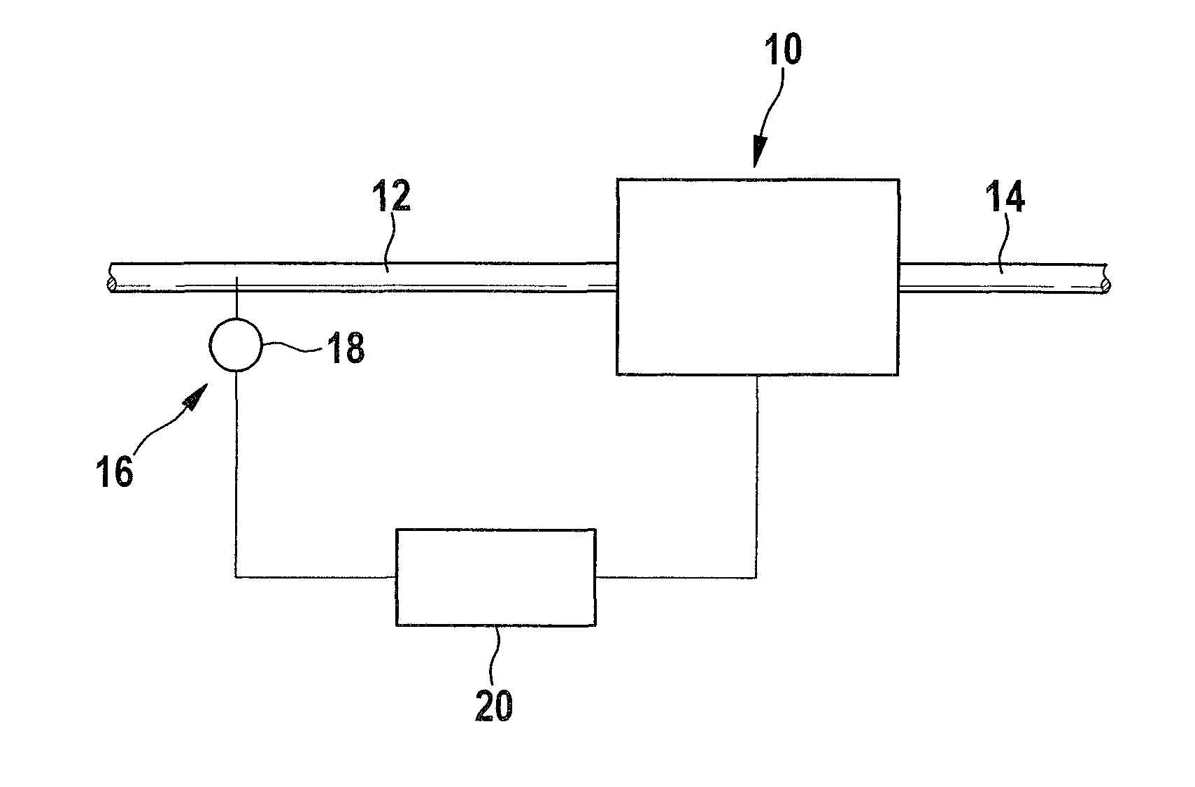
[0038]One specific embodiment of an internal combustion engine is denoted by reference numeral 10 in FIG. 1. Internal combustion engine 10 is designed as a reciprocating internal combustion engine, and has at least one combustion chamber which is supplied with combustion air via a combustion air intake line 12. Exhaust gas generated in the combustion chamber is discharged from the combustion chamber via an exhaust gas discharge line 14.

[0039]Internal combustion engine 10 includes a sensor unit 16 which has a sensor 18 for detecting a pressure or a mass flow of combustion air. Sensor 18 communicates with a control unit 20. At the same time, control unit 20 may be configured for actuating an ignition unit and / or a fuel injector of internal combustion engine 10.

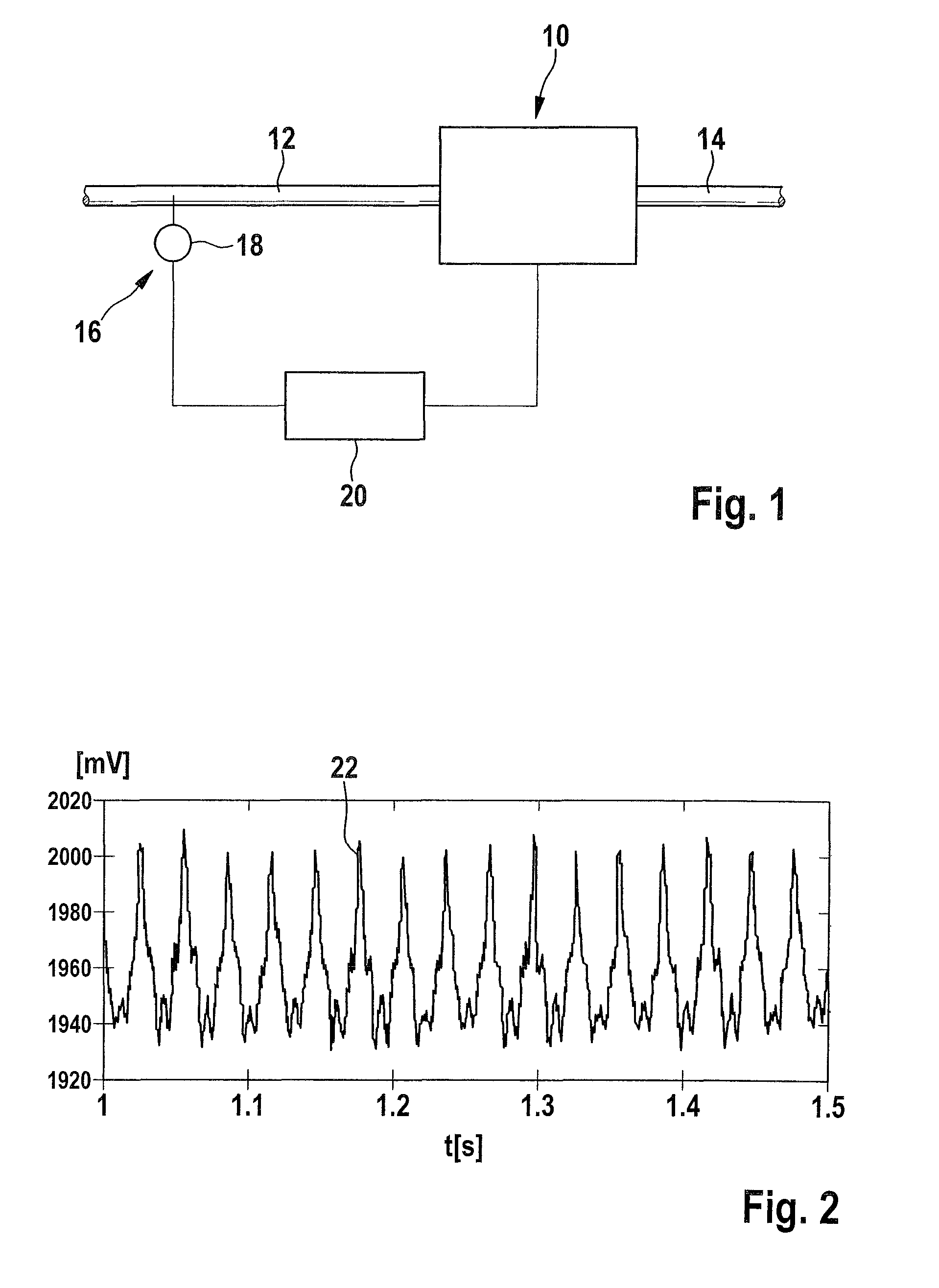
[0040]For the exemplary embodiment described below, sensor 18 is a pressure sensor, for example, a sensor which detects a boost pressure.

[0041]FIG. 2 shows an example of a variation over time 22 of the value of a boost pressure,...


PUM


Abstract

A method for diagnosing a sensor unit of an internal combustion engine, in which an output signal of the sensor unit is compared to a setpoint value which is specified independently from the output signal. The setpoint value relates to a periodic characteristic, and the variation over time of the value of the output signal of the sensor unit or a variable which is derived from the value variation over time is analyzed with regard to this periodic characteristic.

Description

RELATED APPLICATION INFORMATION[0001]The present application claims priority to and the benefit of German patent application no. 10 2009 027 400.6, which was filed in Germany on Jul. 1, 2009, the disclosure of which is incorporated herein by reference.FIELD OF THE INVENTION[0002]The present invention relates to a method for diagnosing a sensor unit of an internal combustion engine, in which an output signal of the sensor unit is compared to a setpoint value which is specified independently from the output signal. Moreover, the exemplary embodiments and / or exemplary methods of the present invention relates to a computer program and a control unit for an internal combustion engine.BACKGROUND INFORMATION[0003]For the optimal control of an internal combustion engine, a variety of sensor units are necessary which are used to detect, for example, pressures or mass flow rates of combustion air supplied to the internal combustion engine, or of exhaust gas or recirculated exhaust gas. Since ...

Claims


Application Information

Patent Timeline
Patent Type & Authority Patents(United States)
IPC IPC(8): G01M15/02
CPCY02T10/40F02D2200/0406F02D41/187F02D41/222
Inventor WAGNER, HORSTLUX, SLOBODANKAHOERNER, MARTIN
Owner ROBERT BOSCH GMBH
Learn More