
Near-field optical recording apparatus, method and medium

a near-field optical recording and near-field technology, applied in the field of near-field optical recording apparatus, can solve the problems of cost and complexity of lenses, general limitations of optical data storage, etc., and achieve the effects of large width, reduced manufacturing costs, and reliable modulation of gap error signals

Inactive Publication Date: 2011-03-17
THOMSON LICENSING SA
View PDF13 Cites 0 Cited by
  • Summary
  • Abstract
  • Description
  • Claims
  • Application Information

AI Technical Summary

Benefits of technology

[0007]Preferably, the signal processor is a high-pass filter. As the data signal is a high-frequency modulation of the gap error signal, it can easily be derived from the gap error signal by a high-pass filter. An additional low-pass filter is advantageously provided for deriving the gap error signal from the output signal of the detector. This allows to use the gap error signal for focus control.
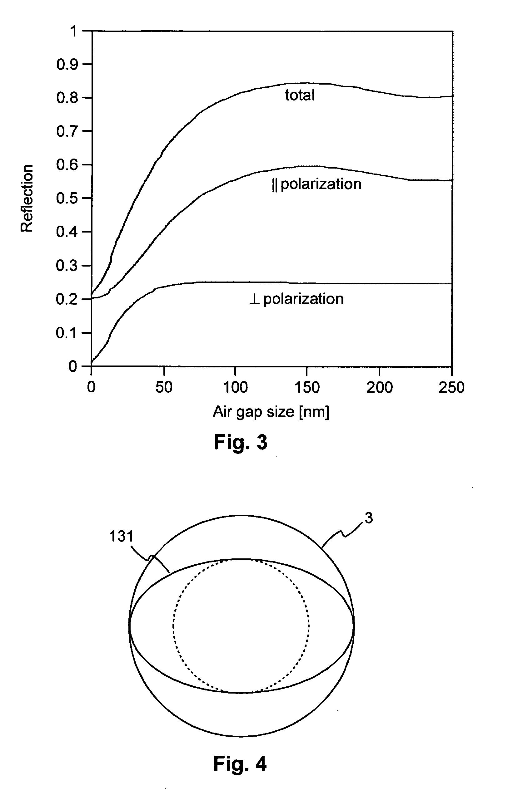
[0009]Preferably, an inner radius ri of the reading light beam is ri=f / nsil and an outer radius ro of the reading light beam is ro=f*NA, where f is the focal length of a reading lens system having an objective lens and a solid immersion lens, NA is the numerical aperture of the reading lens system, and nsil is the refractive index of the solid immersion lens. If these conditions are fulfilled, the modulation due to the evanescent coupling of the pits and the near-field is maximized.
[0010]According to still a further aspect of the invention, a near-field optical recording medium with pits is provided, which are formed by elevations or depressions of the surface of the optical recording medium. Favorably the pits have a height or a depth between 10 nm and 30 nm. As the pits are arranged at the surface of the optical recording medium, they lead to a modulation of the gap error signal. The proposed height or depth is sufficient to generate a reliably detectable modulation of the gap error signal. At the same time the small height or depth simplifies the manufacturing of the near-field optical recording medium.
[0011]Advantageously, the pits have a particularly large width, preferably larger than 0.5λ / NA, where λ is a wavelength used for readout and NA is a numerical aperture used for readout. For example, for a reading wavelength of 405 nm and a numerical aperture of 1.5 the width of the pits is larger than 270 nm. In this way the pits cover a large portion of the reading light spot, which improves the coupling of the evanescent waves into the pit. In addition, the particularly wide pits further facilitate manufacturing of the near-field optical recording medium.
[0012]Favorably, the near-field optical recording medium does not have a reflective coating. The detection mechanism based on coupling of evanescent waves allows to use a near-field optical recording medium without any reflective coating. A simple molded plastic substrate is sufficient. Apparently this reduces the number of manufacturing steps for the near-field optical recording medium, and hence the manufacturing cost.

Problems solved by technology

Optical data storage is generally limited by the optical resolution of the read / write-system.
Straightforward methods of increasing the optical resolution include using a shorter wavelength and a larger numerical aperture NA, at the costs of lens complexity.

Method used


Image

  • Near-field optical recording apparatus, method and medium
  • Near-field optical recording apparatus, method and medium
  • Near-field optical recording apparatus, method and medium

Examples


Embodiment Construction

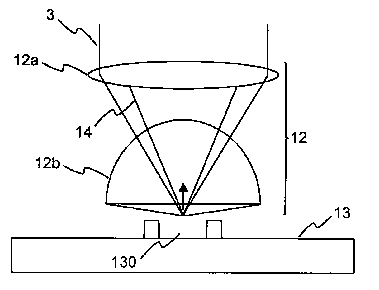
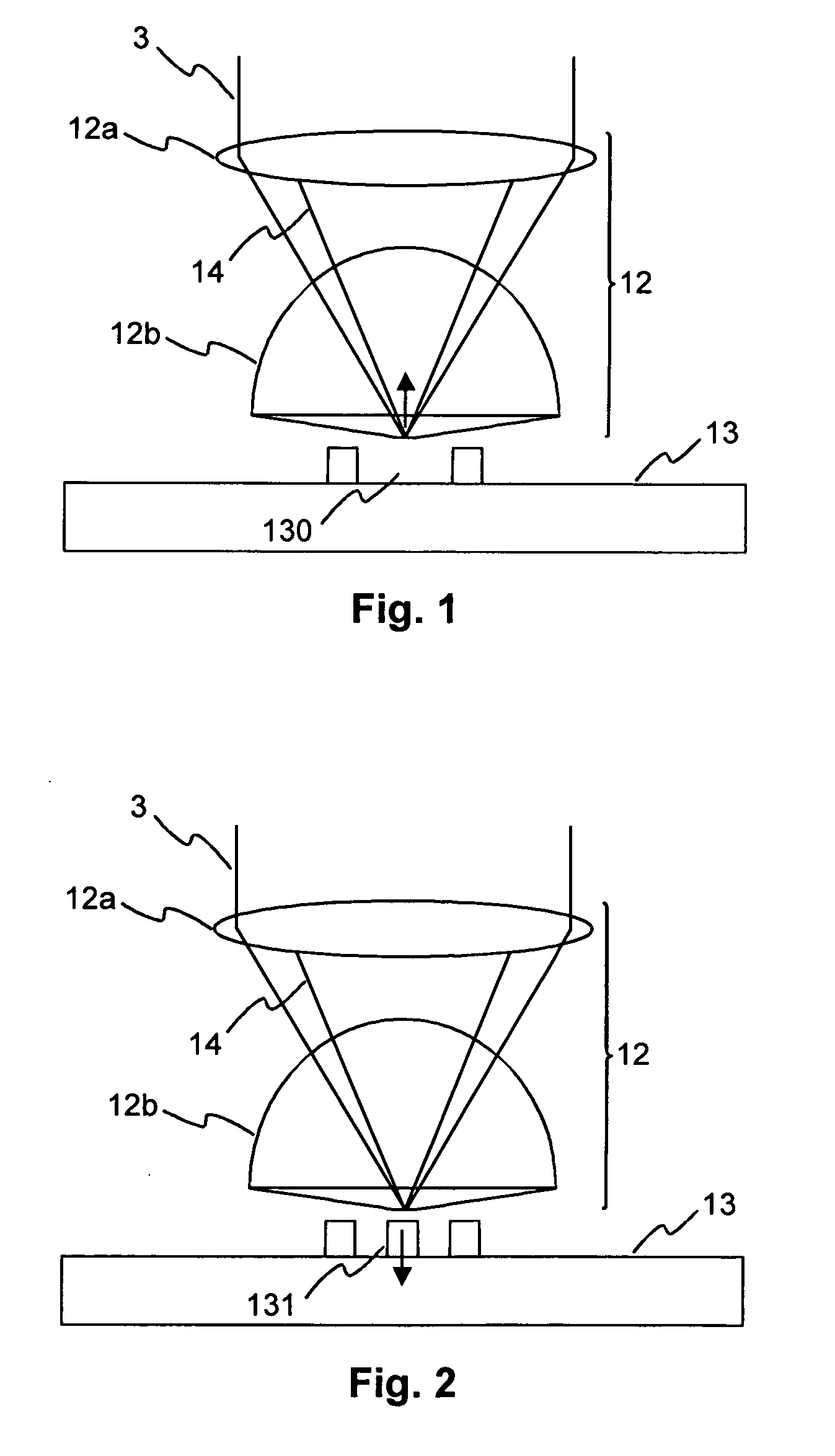
[0021]FIG. 1 shows a solid immersion lens 12b located above a gap 130 of a near-field optical recording medium 13. The solid immersion lens 12b and an objective lens 12a form a reading system 12, which directs a reading light beam 3 onto the surface of the near-field optical recording medium 13. A fraction 14 of the reading light beam 3 is totally reflected at the bottom of the solid immersion lens 12b. This fraction 14 is depicted by an annular cone. The amount of total reflection depends on the distance between the solid immersion lens 12b and the surface of the optical recording medium 13.

[0022]FIG. 2 depicts the solid immersion lens 12b located above a pit 131 of the near-field optical recording medium 13. If the pit 131 is sufficiently close to the solid immersion lens 12b, a part of the energy of the reading light beam 3 that is totally reflected at the bottom of the solid immersion lens 12b is coupled into the pit 131 and continues to propagate into the near-field optical rec...


PUM

PropertyMeasurementUnit
depthaaaaaaaaaa
depthaaaaaaaaaa
widthaaaaaaaaaa

Abstract

An apparatus, a method and a recording medium for optical near-field recording are proposed. The apparatus includes a light source for generating a reading light beam, which is illuminated onto a near-field optical recording medium. The apparatus further includes a detector for generating a gap error signal from a light beam returning from the near-field optical recording medium. A data signal is derived from an output signal of the detector by a signal processor.

Description

FIELD OF THE INVENTION[0001]The present invention relates to a method and an apparatus for optical near-field recording. The invention further relates to a near-field optical recording medium suitable for the near-field optical recording method and apparatus.BACKGROUND OF THE INVENTION[0002]Optical data storage is generally limited by the optical resolution of the read / write-system. Straightforward methods of increasing the optical resolution include using a shorter wavelength and a larger numerical aperture NA, at the costs of lens complexity. Further approaches are narrowing the allowable tilt margins for the optical storage media or reducing the wavelength of the scanning laser into the blue or near-UV range. A different approach for reducing the focus spot size in an optical data storage system is using near-field optics with a high numerical aperture (NA>1). This high numerical aperture is generally achieved by help of a solid immersion lens (SIL). While conventional systems...

Claims


Application Information

Patent Timeline
Patent Type & Authority Applications(United States)
IPC IPC(8): G11B11/00G11B7/135G11B7/24085
CPCG11B7/24085G11B7/1387
Inventor KNITTEL, JOACHIM
Owner THOMSON LICENSING SA
Learn More