Electric utility cart

a technology carts, applied in the field of electric utility carts, can solve the problems of long turning radius, limited utility of certain carts made in the past, and difficult operation and turning of carts in sandy soil, etc., and achieve the effect of increasing or decreasing the cart speed and large load capacity

Active Publication Date: 2014-06-10
BLUE COMET VENTURES
View PDF29 Cites 42 Cited by
  • Summary
  • Abstract
  • Description
  • Claims
  • Application Information

AI Technical Summary

Benefits of technology

[0012]The aforesaid and other objectives are realized by providing an electric utility cart which includes a frame formed from tubular aluminum. A tubular aluminum railing attached to and positioned above the frame provides depth and a large load capacity. Cylindrical holders are joined to the frame and rail which are beneficial for the transportation of fishing equipment such as fishing rods that are placed in the holders and held in a secure, stable fashion. A tongue is releasably attached to the front end of the cart which is held in a sheath joined to the frame. The tongue is L-shaped and along its proximal end a handle is normally affixed. The handle includes a rotatable throttle for adjusting the electric motor by increasing or decreasing the cart speed. A bi-directional switch affixed to the tongue proximate the handle allows the user to drive the cart in either a forward or rearward direction. An auxiliary rack formed from tubular aluminum can be temporarily joined to the cart frame and held in place using a series of clevises and pins which is of particular use while transporting surf boards or other long, heavy items.
[0013]To transport the cart on trips or over long distances, a hitch rod is provided having a head which includes a pair of frame grippers. The hitch rod can be quickly inserted into a standard tubular vehicle hitch for suspending the utility cart thereon and for securing the cart frame to the hitch bar.

Problems solved by technology

Certain carts made in the past have limited utility and are difficult to operate and turn in sandy soils and on uneven terrains.
Other known carts are subject to long turning radiuses and are difficult to maneuver in confined spaces such as inside a warehouse or on a crowded beach.
Other prior carts have relatively small load capacities and are expensive to manufacture and purchase.

Method used


Image

  • Electric utility cart
  • Electric utility cart
  • Electric utility cart

Examples


Embodiment Construction

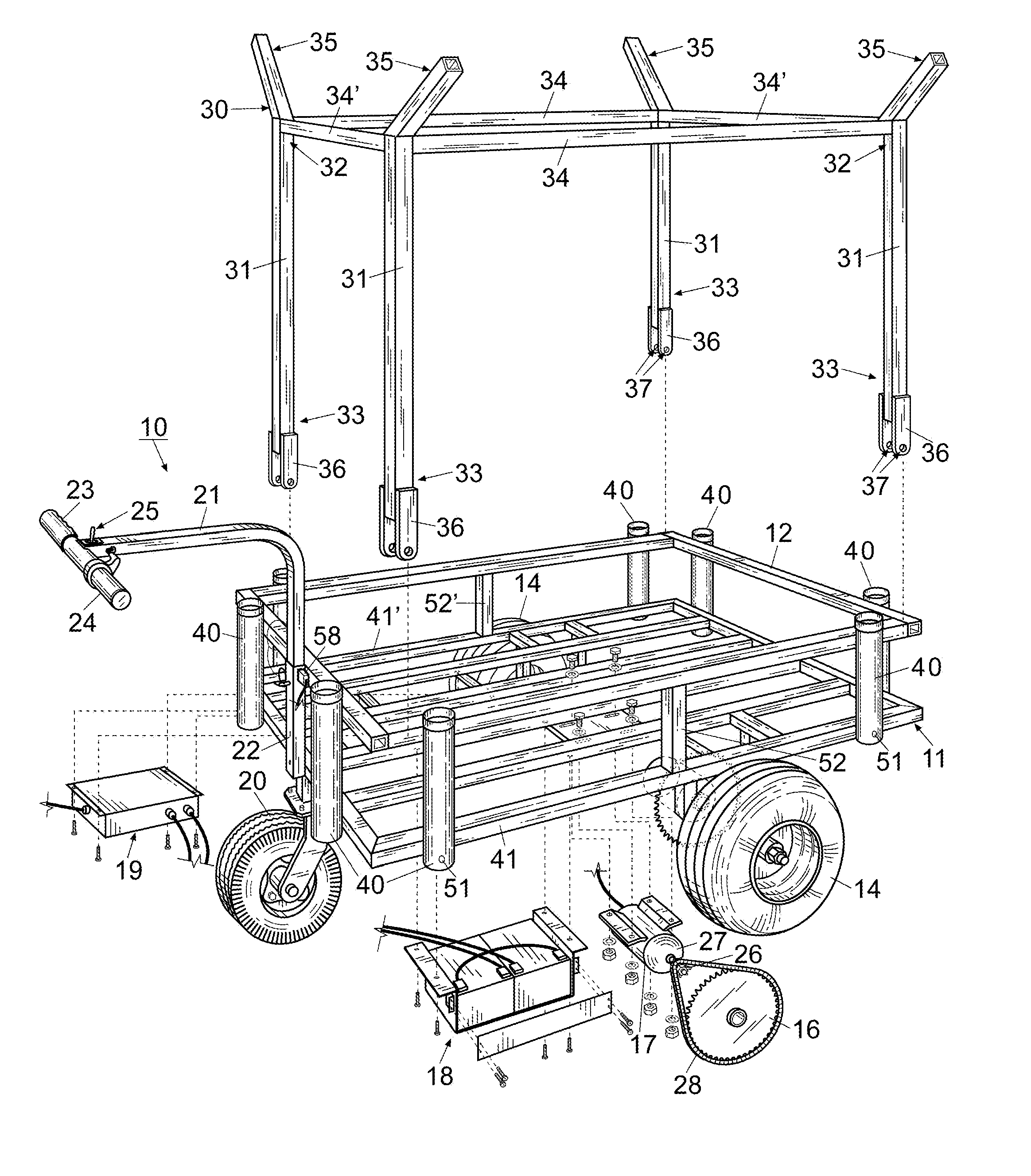
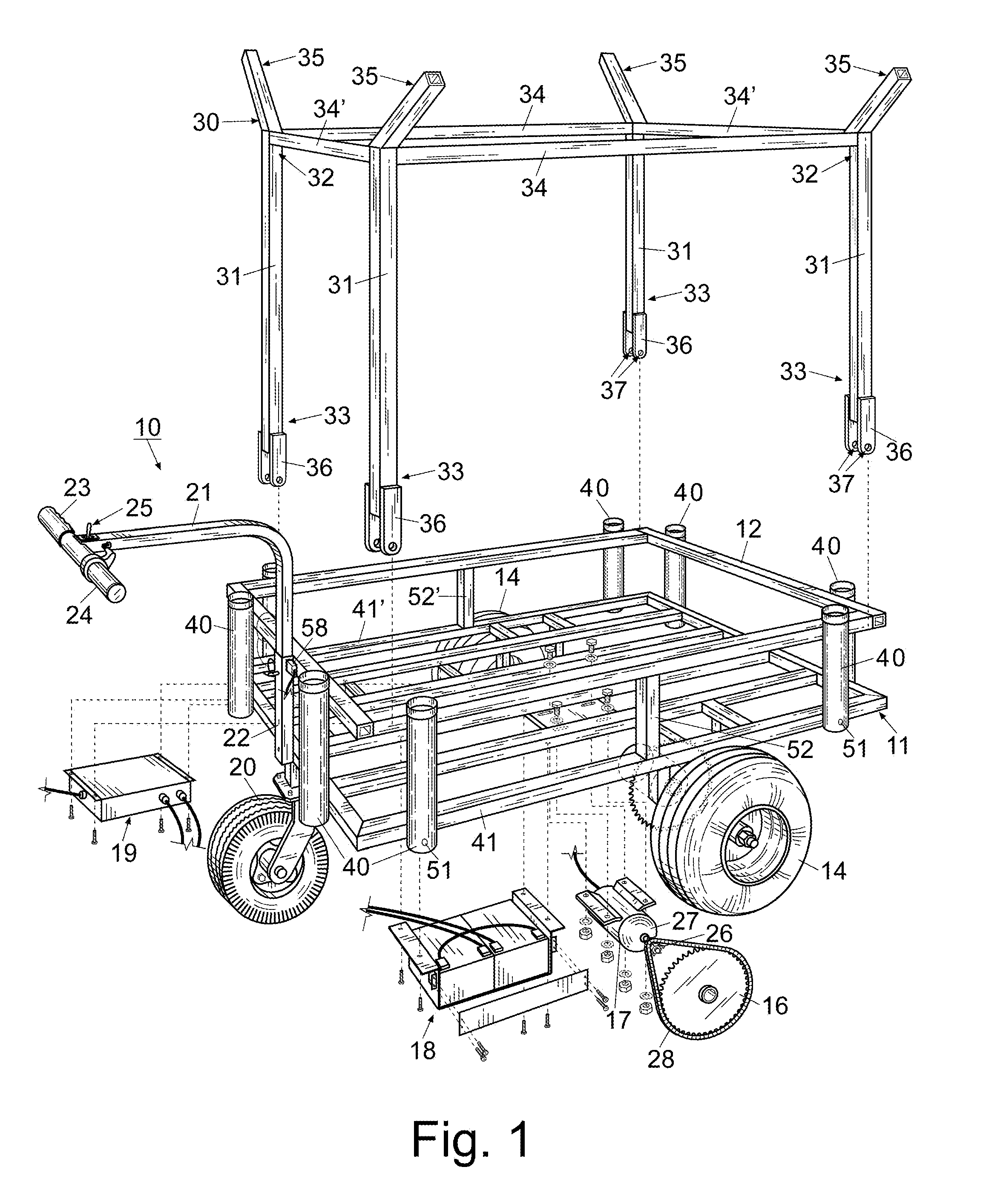
[0023]For a better understanding of the invention and its operation, turning now to the drawings, FIG. 1 shows preferred electric utility cart 10 in a partially exploded view with auxiliary rack 30 as seen in perspective fashion. Utility cart 10 includes a planar rectangular frame 11 and an upper rectangular retaining rail 12. Frame 11 utilizes a series of one inch square aluminum tubular members which are welded together. Retaining rail 12 has the same outer dimensions as frame 11 and is also formed from one inch square aluminum tubular members. Planar rectangular frame 11 as seen in FIG. 6 includes a pair of opposing transverse members 42 (front), 42′ (rear), a pair of opposing outer longitudinal members 41′ and a series of four inner longitudinal members 41. Longitudinal members 41, 41′ are each welded at different ends to transverse members 42, 42′ to form frame 11. Retaining rail 12 as seen in FIG. 5 includes a pair of opposing longitudinal members 71 which are welded at each e...


PUM


Abstract

An electric utility cart to assist in transportation and hauling various items is disclosed. The utility cart includes a handle with a throttle to control the speed of the cart during use. A single 360° rotatable front wheel in combination with a pair of wide rear wheels which are joined to a differential allows the cart to turn in tight circles. A directional switch proximate the handle allows the user to drive the cart in either a forward or rearward direction. An auxiliary rack can be mounted on the cart as needed for carrying surf boards or other large items. A hitch rod allows the cart to be suspended and transported by a conventional vehicle such as a car, SUV or pickup truck having a typical tubular hitch.

Description

FIELD OF THE INVENTION[0001]The invention herein pertains to a utility cart and particularly pertains to a utility cart which is motorized and hand directed. The cart has many advantages over other carts used on sandy soils and uneven terrains due to its wide tires and short turning radius.DESCRIPTION OF THE PRIOR ART AND OBJECTIVES OF THE INVENTION[0002]In recent years increasing numbers of consumers have realized the advantages of using electric or motorized carts to assist in various tasks. Such tasks may be for example transporting fishing gear from a vehicle to a desired site on a dock or beach. Other tasks may include transporting of lawn tools, supplies and equipment. Certain other tasks involve moving items to or from a store room or general storage area. Hunters and other outdoors men often utilize utility carts for carrying game or supplies, such as shown in U.S. Publication No. 2008 / 0197608.[0003]Certain carts made in the past have limited utility and are difficult to ope...

Claims


Application Information

Patent Timeline
Patent Type & Authority Patents(United States)
IPC IPC(8): B62D51/04
CPCB62B5/0033B62B5/0003B62D51/04B62B2202/52B62B2202/403B62B3/02B62B5/0046
Inventor DUNBAR, CHRIS, T.
Owner BLUE COMET VENTURES
Why Eureka
Try Eureka