Method and apparatus for blending process materials

a technology of process materials and blending equipment, applied in the direction of chemistry apparatus and processes, transportation and packaging, mixing, etc., can solve the problems of reducing the efficiency of the blending process itself, and rendering it useless for its intended application. , to achieve the effect of improving the mixing efficiency and reducing the overall system cos

Active Publication Date: 2014-06-10
MEGA FLUID SYST
View PDF12 Cites 0 Cited by
  • Summary
  • Abstract
  • Description
  • Claims
  • Application Information

AI Technical Summary

Benefits of technology

The present invention is an improved apparatus for blending process materials. It increases the contact area between wet and dry materials, allowing for better mixing efficiency. The invention also reduces system costs by using a single solid feeder with multiple process material tanks. It allows for remote blending, adjustable wetted surface area, decreased set-up time, and reduced process variability. The invention also provides closed loop control of solid / liquid spiking at a combined blend / distribution tank.

Problems solved by technology

In many applications, even minor process variations may lead to significant differences in the batch of blended process materials, potentially rendering it useless for its intended application.
There are a number of disadvantages to this type of prior art bulk delivery system.
First, the blending process itself suffers from some inherent inefficiency.
Significantly, as the solid material from the solid feeding element is added to the liquid in the blending tank, the contact area for wetting the added solid material is limited to the surface of the liquid in the tank.
This slows the rate at which solid material can be added to the tank.
The localized forced-convection mixing of the solids into the liquid in a prior art system can also be relatively inefficient for fine, hydrophobic solids, due in part to the tendency of some solid materials to float on the surface of the liquid rather than being entrained into the circulating liquid in the blending tank.
The solid feeder is quite expensive when compared to the other components, and the prior art system requires a solid feeder for each process material tank used for blending or mixing.
The cost associated with a solid feeder thus increases in one-to-one multiples with the number of active blending tanks and distribution tanks if spiking functions are present.

Method used


Image

  • Method and apparatus for blending process materials
  • Method and apparatus for blending process materials
  • Method and apparatus for blending process materials

Examples


Embodiment Construction

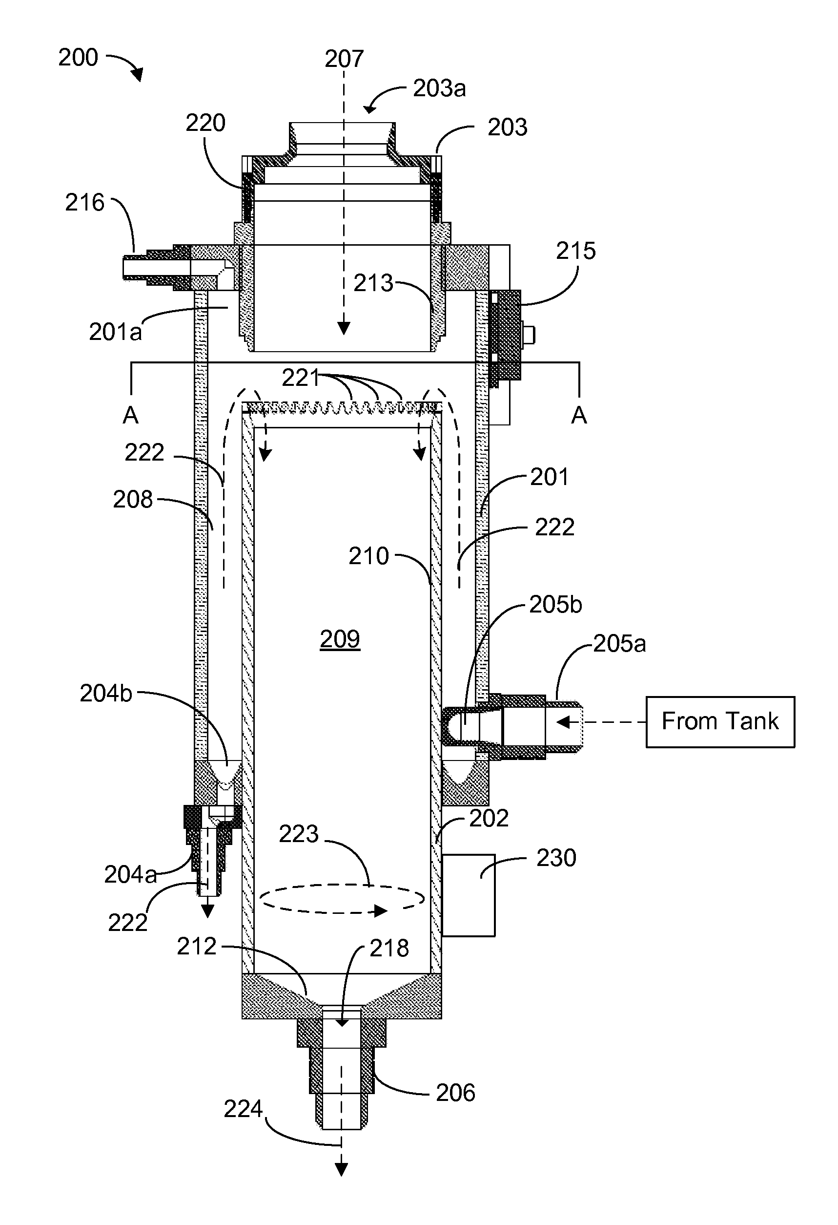
[0027]Preferred embodiments of the present invention are directed to a process material contacting system to increase wetted surface area for liquid contact as well as increase forced convective mixing efficiency of the liquid mixture. Use of the novel process material contacting apparatus described herein also allows one solid feeding element to serve multiple process material tanks, thus reducing overall system costs and decreasing set-up time / process variability while increasing operational efficiency. According to a preferred embodiment of the present invention, rather than adding a process material to a volume of liquid held in a blending tank, the added process material is remotely blended with the liquid outside the process material tank.

[0028]One preferred embodiment of a process material blending apparatus according to the present invention is shown in FIGS. 2-4. The blending apparatus of FIGS. 2-4 can be referred to as a solid-liquid contactor (“SLC”). The SLC includes a f...


PUM


Abstract

An improved method and apparatus for blending process materials. Preferred embodiments of the present invention are directed to a process material contacting system to increase wetted surface area for liquid contact as well as increase forced convective mixing efficiency of the liquid mixture. Use of a novel process material contacting apparatus allows one solid feeding element to serve multiple process material tanks, thus reducing overall system costs and decreasing set-up time / process variability while increasing operational efficiency. According to a preferred embodiment of the present invention, rather than adding a process material to a volume of liquid held in a blending tank, the added process material is remotely blended with the liquid outside the process material tank.

Description

[0001]This application claims priority from U.S. Provisional Patent Application No. 61 / 214,139 filed on Apr. 20, 2009, which is herein incorporated by reference in its entirety.TECHNICAL FIELD OF THE INVENTION[0002]The present invention is directed to a method and apparatus for blending process materials, more particularly to a process material contacting system to increase wetted surface area for liquid contact as well as increase forced convective mixing efficiency of the liquid mixture.BACKGROUND OF THE INVENTION[0003]Bulk delivery systems are used, for example, to supply process equipment in the pharmaceutical, cosmetic, and semiconductor industries with blended process materials such as liquid chemicals or slurries. In the semiconductor industry, blended process materials are typically prepared using batch production systems including a blending subsystem and a distribution subsystem. In the blending subsystem, process materials are added to a blending vessel or tank. For examp...

Claims


Application Information

Patent Timeline
Patent Type & Authority Patents(United States)
IPC IPC(8): B01F5/10
CPCB01F5/248B01F5/0057B01F15/0227B01F3/1271B01F23/59B01F25/85B01F35/717B01F25/10
Inventor KANDIYELI, DAVID D.WILLIAMS, QUAY ISSAC GENECAVINAW, BARRY KENNEDYBOLEY, JR., CHARLES RICHARD
Owner MEGA FLUID SYST
Why Eureka
Try Eureka