Stackable surface module for a wall surface

a technology of a wall surface and a stacking module, which is applied in the direction of load-supporting elements, structural elements, building components, etc., can solve the problems of not being able to remove elements on both sides (left/right and front/back) from the erected wall without removing, and the module is therefore unsuitabl

Active Publication Date: 2014-06-17
ZINSER KLAUS
View PDF15 Cites 1 Cited by
  • Summary
  • Abstract
  • Description
  • Claims
  • Application Information

AI Technical Summary

Benefits of technology

[0019]The general advantage of the invention is in the construction of especially thin, toppling-resistant walls made from surface modules. In the current state-of-the-art, quite thick blocks are used in comparison with the said surface modules. The use of further layers allows an increase in the module thickness in the y-direction, which raises material costs without bringing any additional stabilization effect. With the present thin construction, the y-axis locking in both directions normal to the wall area, can be achieved with a lower wall thickness. This can offer decisive advantages, e.g. in the building of sloping or overhanging walls, for example in the building of cupolas or other building designs with special earthquake-proof qualities.
[0020]The basic surfaces of the module are generally present independently of the interlocking points. The additional upwards and downwards-projecting protuberances or hollows of the courses at the interlocking points are overlaid onto the basic surfaces and therefore form additional interlocking surfaces in the x / y-plane and intermediate surfaces in the x / z-plane. The other arrangements of the basic surfaces remain unaffected.
[0021]A locking in both y-directions normal to the wall or shell surface means that the particular joined modules at these points in the assembled condition allow no relative movement in the y-direction, with the exception for a small optional amount of play.
[0022]This means that bending moments can be transferred to the modules. At the interlocking points, forces can be transferred or dissipated. This means that the wall surfaces made available can absorb bending forces and distribute these over the wall surface. This is important with earthquakes but also for high walls exposed to wind forces or vibrations (updraft power plants). Rigid connections using mortar regularly threaten to break or a form cracks. On the other hand, the wall modules must be secured against permanent shifts or the breaking out of individual modules from the wall. In this case, the interlocking points lock the movement in the y-direction, while the basic forms of the surface module prevent movements in the masonry in the x-direction.
[0023]The basic surfaces of the module perimeter are the basic surfaces of the upper side, underside as well as the left and right lateral surfaces. These are therefore located between the front side and the rear side of the surface module. These surfaces form a perimeter around the said module.
[0024]An interruption in the interlocking point or points along the module perimeter means that the modulation of the upper, lower or side basic surfaces for the generation of the interlocking point is not continuous along the entire module perimeter. Because of the interruption, at least at one point along the module perimeter a surface is generated that is continuously parallel to the y-axis.

Problems solved by technology

This results in strong masonry, but with the disadvantage that the wall can no longer be altered and can only absorb forces to a limited extent, especially bending moments and buckling.
A further problem is that, in the case of a joint, e.g. with glue or mortar, the weakness of each individual module element determines the overall properties of the complete wall area—so that no stabilizing synergies develop.
In the normal case, it shall not be possible to remove elements on both sides (left / right and front / rear) from the erected wall without removing the topmost level.
This module is therefore unsuitable for the present method of stacking to be achieved with the clamping effect as described in the following.
However, the modules have disadvantages.
An interlocking groove running around the entire perimeter wastes material and is difficult to manufacture.
In addition, it shall not be possible for the wall modules to move sideways relative to each other.
The use of further layers allows an increase in the module thickness in the y-direction, which raises material costs without bringing any additional stabilization effect.
Rigid connections using mortar regularly threaten to break or a form cracks.
However, it is not desirable to use more material than really necessary.
Ultimately, complete interlocking allows less flexibility in the variation of the surface shapes and wall thicknesses.
Curves in the modules are much more difficult to realize when the interlocking points are over the full thickness and the modules are more difficult to join together than when the interlocks have only to be brought together at several predefined points.
However, the depth should not be so great that the upper module section becomes so thin that the material stability is no longer guaranteed and the module becomes too fragile.
Angular specifications of more than 90° are therefore not possible.
Specifications of angles greater than 90° are therefore not possible.
Non-planar or additional steps or recesses in the lateral surfaces lead to opposing surfaces in the wall no longer being equal.
In addition to the locking effect, the larger surface per unit volume of the module therefore also increases the static friction of the modules.
Stress fields can arise here under tensile loading which can lead to extensions breaking under load.
Smaller cutouts with correspondingly smaller extension pieces are more difficult to manufacture and less resistant to breaking off than larger extension pieces with high material thickness.
This form however has a large volume for the total locking surface achieved.
This module is also not protected against tensile stress in the x-direction.
As a result, a y-axis locking with the next module is not possible at this point.
There is a danger here that the neighboring modules slide apart.
A lock at only one point would however have the disadvantage that around this point the wall could absorb the rotational forces and the loosening of a module under high compressive or tensile forces would be possible.
However, to be able to join the modules to each other from above, they may not have any undercuts in the z-direction.
The toppling in this direction is naturally less of a problem, but shifts of the module surfaces relative to each other, e.g. during earthquakes are also undesirable.
Pure concrete is not very strong in withstanding tensile loads.
The main approach here is that the manufacture and re-use of existing modules is very cost-effective, whereas a modification to the module without destroying it, in the simplest case by melting down, is considerably more expensive.

Method used


Image

  • Stackable surface module for a wall surface
  • Stackable surface module for a wall surface
  • Stackable surface module for a wall surface

Examples


example 1 (

Angular U-shape)

[0433]The module is made of plastic and has a constant thickness of 1.5 cm in the y-direction. The maximum extent in the x-direction is 30 cm. The maximum extent in the z-direction is 12 cm. The module has an angular U-shape. Starting with a rectangular basic form having the above dimensions, a rectangular recess is cut out from the lower part in the middle of the x-direction with a length of 15 cm (in the x-direction), a width of 6 cm (in the z-direction) and a thickness of 1.5 cm (in the y-direction). In the following, the module is described when being viewed from the front. The front profile is constant in the y-direction. The edge lengths of the surfaces of the module in the counterclockwise direction are listed in the following, starting with the lower left corner of the module. The angle information is in brackets, starting from the end point of the previous edge corresponding to the normal degree distribution of a unit circle in 360° in the counterclockwise d...
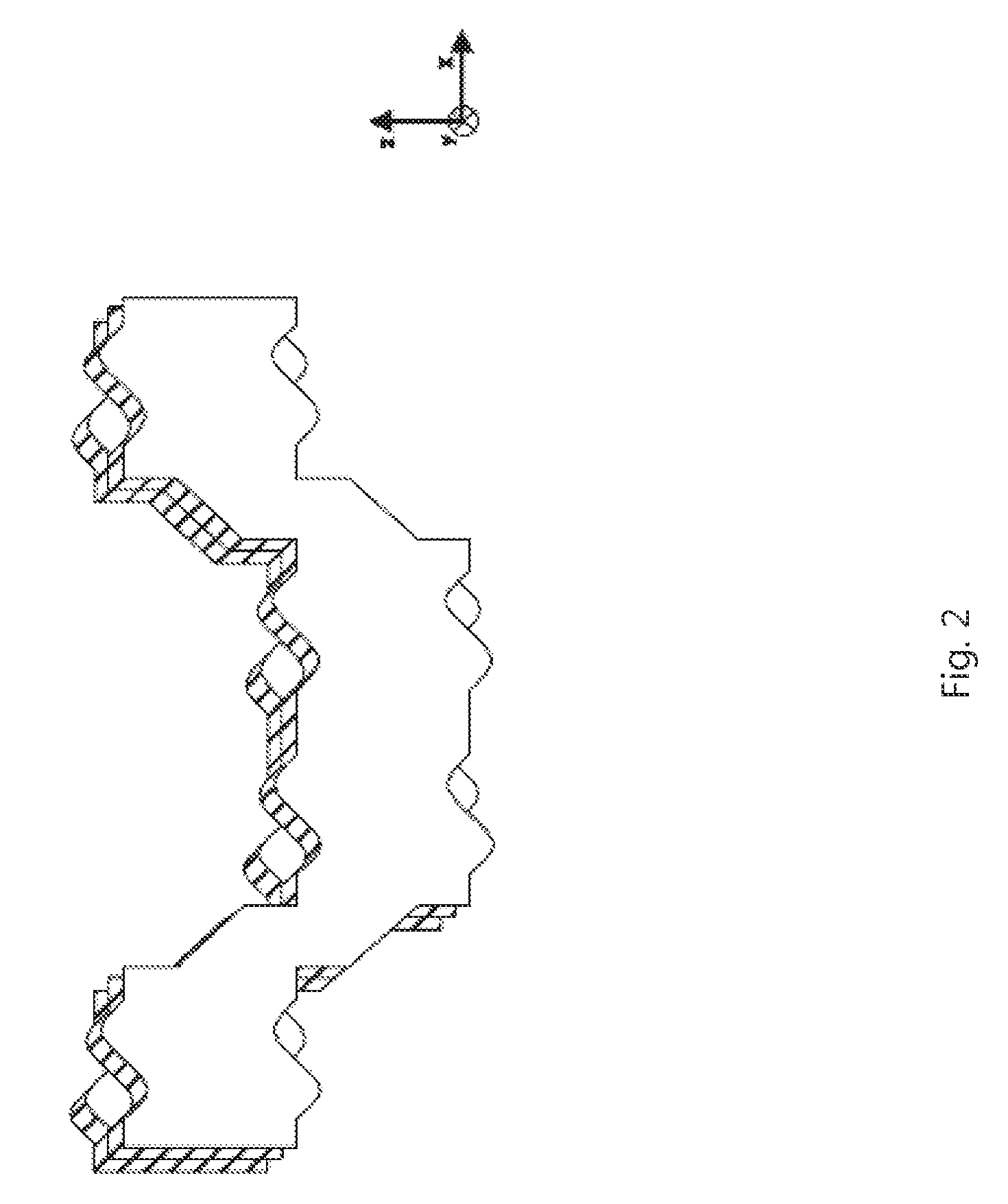
example 2 (

Simple H-shape)

[0435]The module according to the invention is made of plastic and has a constant thickness of 1.5 cm in the y-direction. The maximum extent in the x-direction is 30 cm. The maximum extent in the z-direction is 24 cm. The module is H-shaped. Starting with a rectangular basic form having the above dimensions, a rectangular recess is cut out from the lower and upper parts in the middle of the x-direction each with a length of 15 cm (in the x-direction), a width of 8 cm (in the z-direction) and a thickness of 1.5 cm (in the y-direction). In the following, the module is described when being viewed from the front. The front profile is constant in the y-direction. The edge lengths of the surfaces of the module in the counterclockwise direction are listed in the following, starting with the lower left corner of the module. The angle information is in brackets, starting from the end point of the previous edge corresponding to the normal degree distribution of a unit circle in...

example 3 (

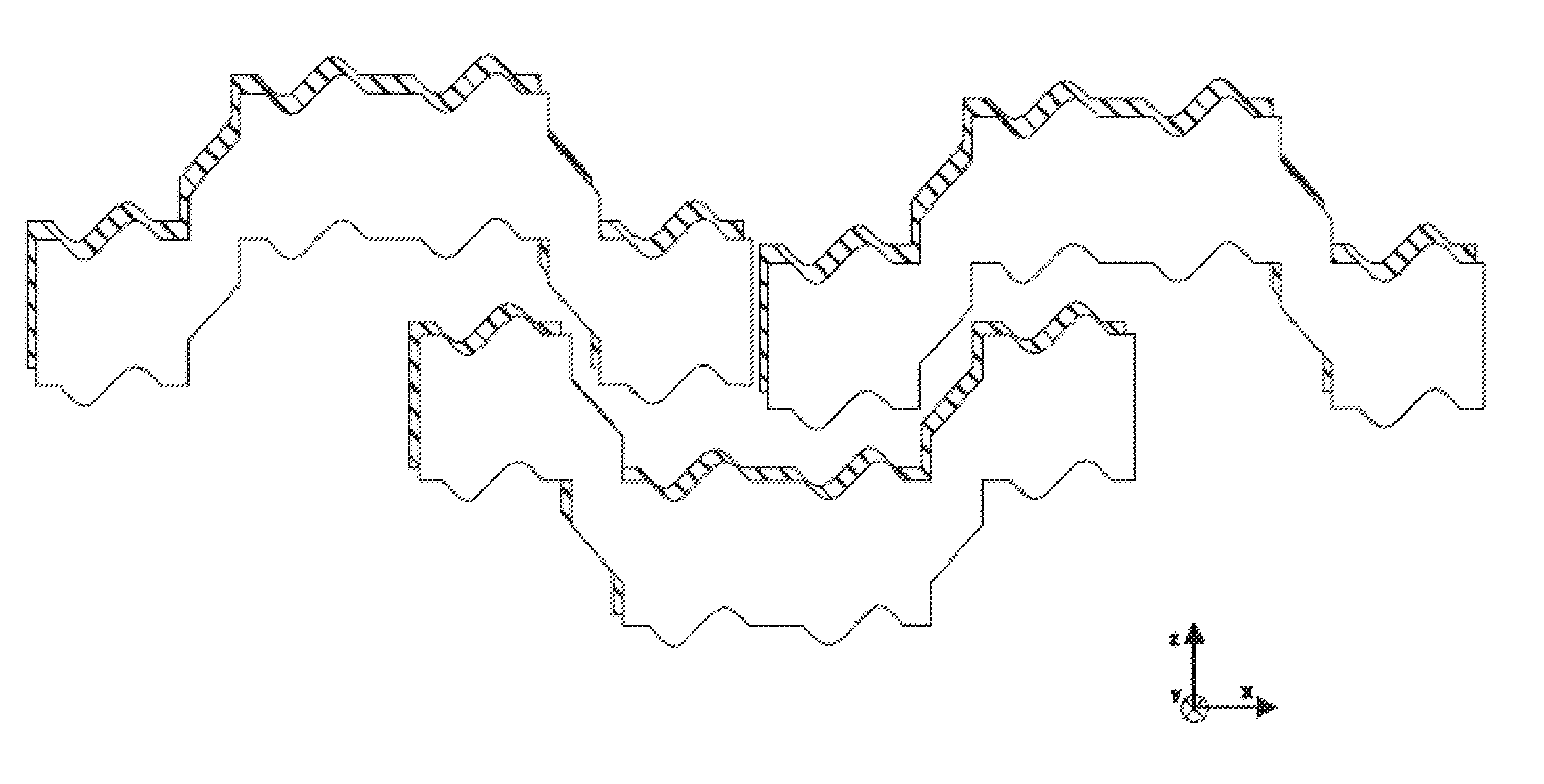
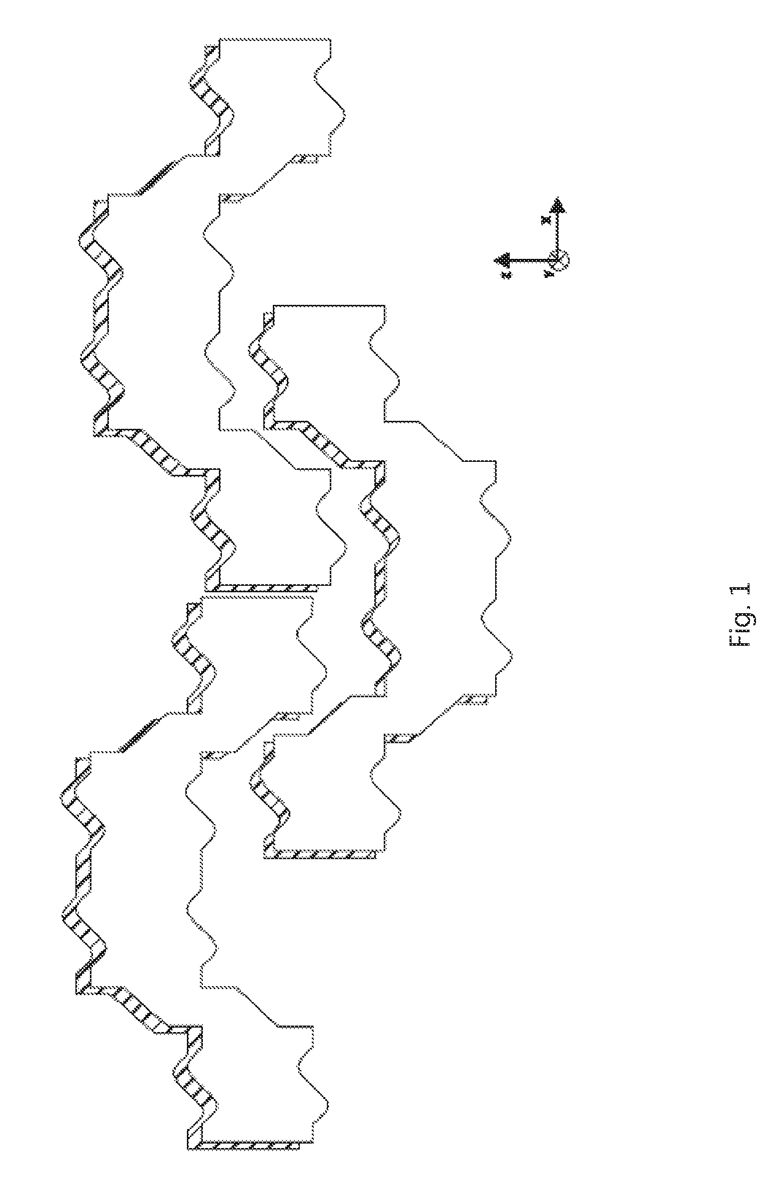
H-shape with Sinusoidal Horizontal Edges)

[0439]A module with sinusoidal horizontal surfaces can be modeled on the basis of the H-shaped module in Example 2. The module is also made of plastic and has in principle the same basic surfaces as in Example 2.

[0440]In a variant made of concrete, all lengths (as well as heights and thicknesses must be multiplied by a factor of 3 to 15. In a variant made of wood, the lengths must be multiplied by a factor of 2 to 7.

[0441]Here, each of the six horizontal surfaces (with an angle of 0° or 180°, i.e. UALE, SI, UARE, OARE, II and OALE) has at least one sine wave. The lower and upper outer edges of the extensions (UALE, UARE, OARE and OALE) are so formed that the sine wave starts to rise at the straight distance of 0.75 cm from the left corner of the edge. The gain in area in the case of an upper edge or the loss of area in the case of the lower edge in comparison with Example 2 increases sinusoidally in the x-direction up to a maximum height of 1...


PUM


Abstract

A stackable surface module is provided for a wall surface that can be both erected and dismantled. The stackable surface module is especially useful in certain applications, such as for earthquake-resistant walls, a cupola, a bridge, a site fence, a noise protection wall, an upwind power station, a heat exchanger or a coastal protection wall.

Description

CROSS-REFERENCE TO RELATED APPLICATIONS[0001]This application is a U.S. National stage application of International Application No. PCT / DE2012 / 000574, filed May 30, 2012.BACKGROUND OF THE INVENTION[0002]1. Field of the Invention[0003]The invention relates to a stackable surface module for a wall surface that can be erected and dismantled (reversible) and the use of the surface module for particular applications, especially for earthquake-resistant walls, a bridge, a compost shed, a site fence and noise-protection wall, an upwind power plant, heat exchangers or a coastal protection wall—also for walls of buildings.[0004]2. Background Information[0005]To erect such a wall or similar edifice, it is well known that individual building blocks or wall modules are to be laid one on another and joined together with a substance which hardens out, e.g. mortar. In this, a building block is to be so laid on two adjacent building blocks that it covers half of each of the two blocks. This results...

Claims


Application Information

Patent Timeline
Patent Type & Authority Patents(United States)
IPC IPC(8): E04C3/00E04B2/00
CPCE04B2/12E04C2/46E04B2002/0226
Inventor ZINSER, KLAUS
Owner ZINSER KLAUS
Why Eureka
Try Eureka