Medical electrode with printed shielded feed line

Active Publication Date: 2014-06-17
LEONH LANG
View PDF21 Cites 4 Cited by
  • Summary
  • Abstract
  • Description
  • Claims
  • Application Information

AI Technical Summary

Benefits of technology

[0013]The object of the present invention is therefore to provide an improved medical electrode compared to the prior art. In particular the hitherto known (shielded) feed cables should be easier to handle. In addition the electrical connections between the electrode head a

Problems solved by technology

Medical electrodes for introducing and discharging electric currents into and from the human or animal body have been known for a considerable length of time.
For a connection that integrates the electrode head into the shielding, the connections and associated plugs either have to be configured in a relatively complicated manner, as is illustrated in EP 1 569 551 B1, or the plug additionally has to be designed as a shield overlapping the electrode head, which means that this region is heavy and inflexible and moreover is qualitatively inferior to a shielding integrated into the electrode.
The disadvantage therefore is basically the fact that the production of a medical electrode with an electrode head and integrated, unshielded and round cable feed line

Method used


Image

  • Medical electrode with printed shielded feed line
  • Medical electrode with printed shielded feed line
  • Medical electrode with printed shielded feed line

Examples


Embodiment Construction

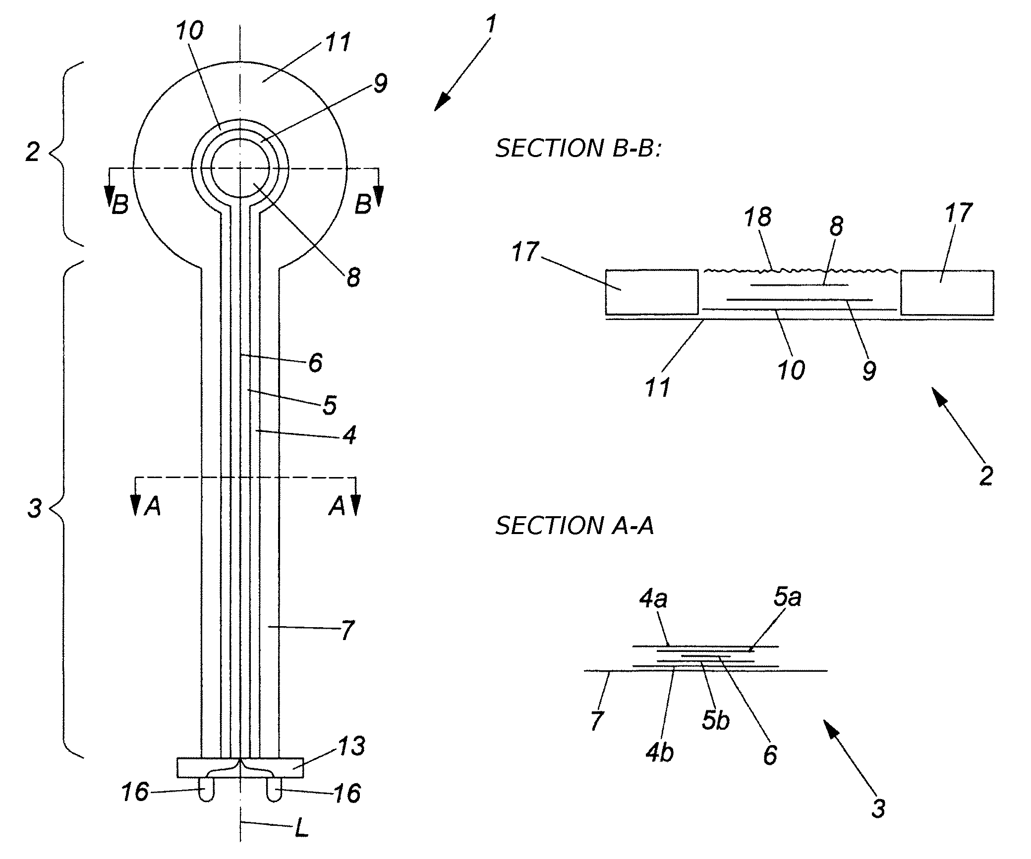
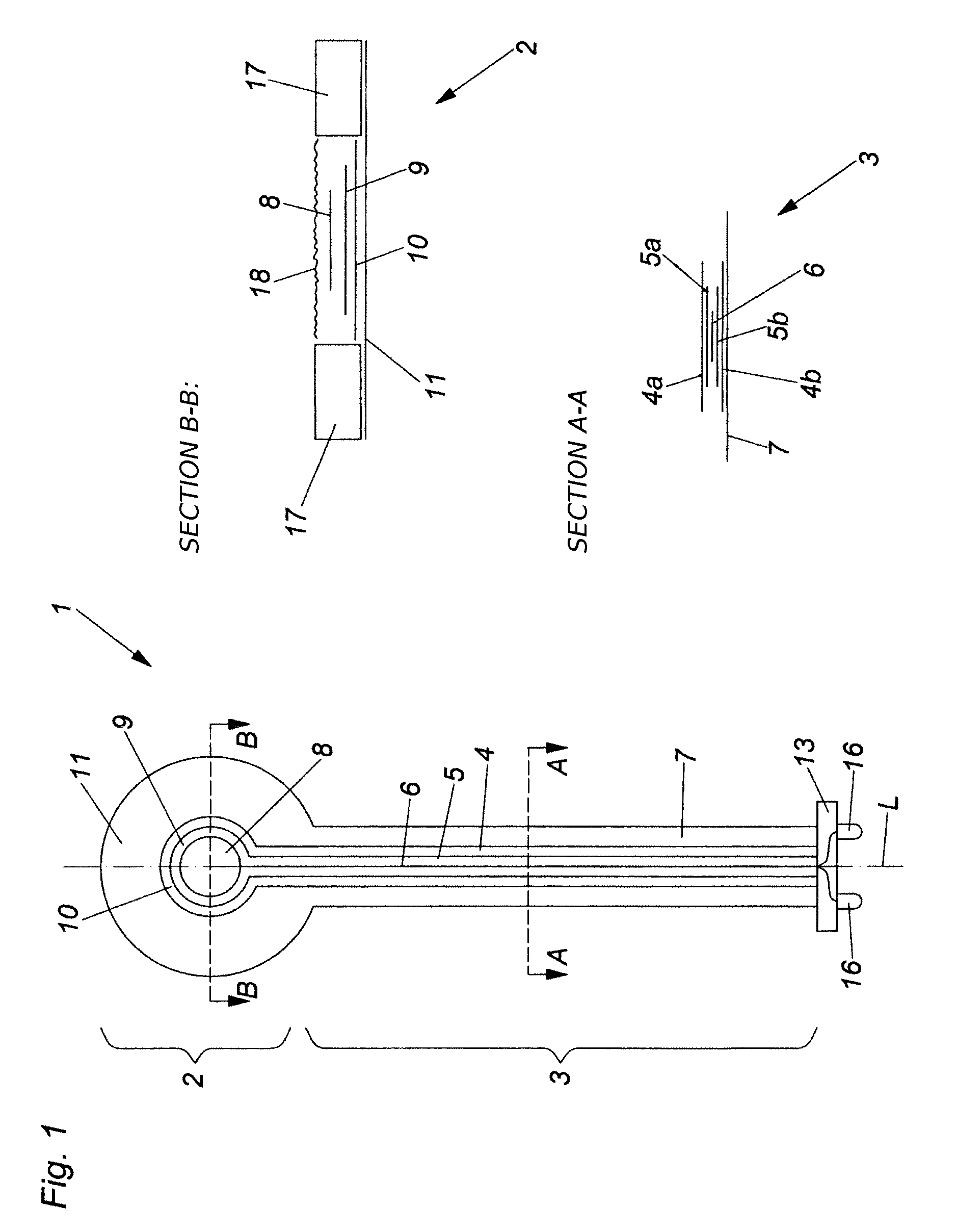
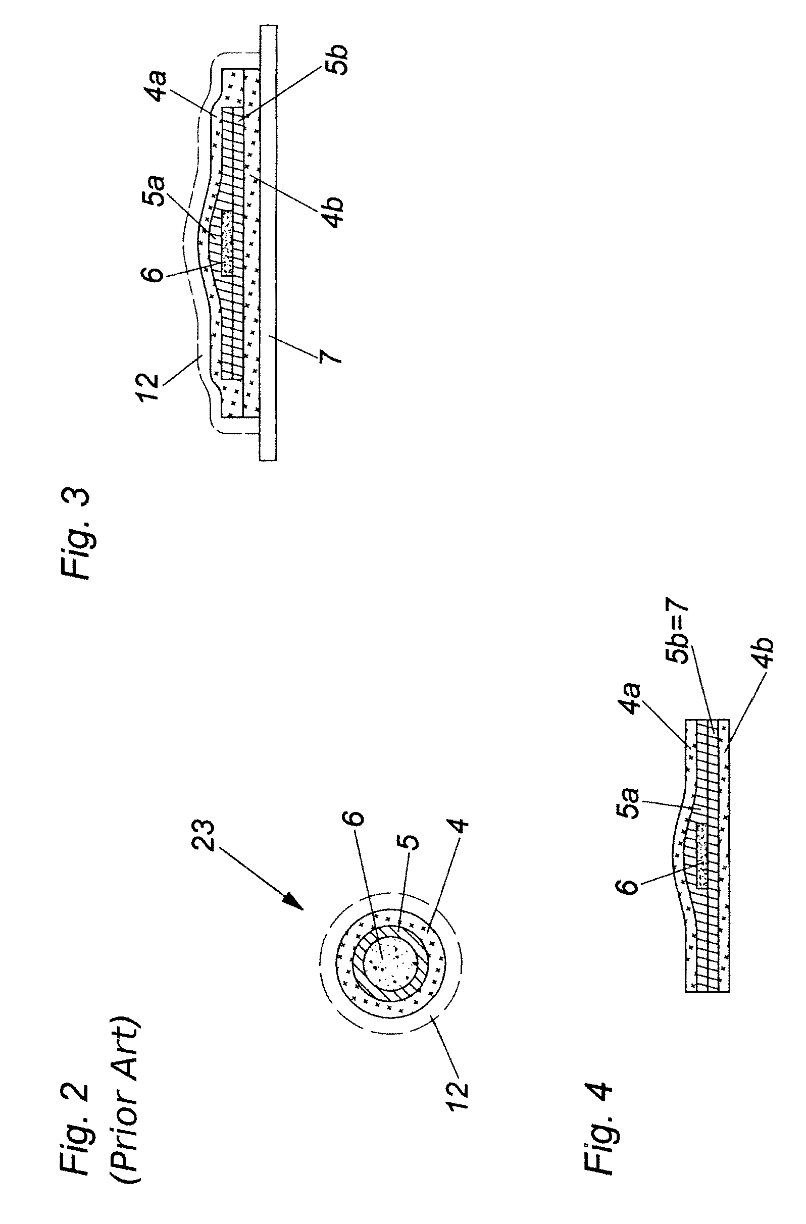
[0016]An implementation variant may be envisaged in which the substrate element is implemented as a metalized film so that the substrate element already acts as a shield over certain regions. The electric conductor together with the dielectric are applied, preferably printed, onto this metalized film, and then first of all the printed part of the shield is printed on and is joined to the metalized film so that the electric conductor together with the dielectric is entirely surrounded transverse to the longitudinal direction of the feed line by the (two-part) shielding.

[0017]According to a particularly preferred embodiment of the present invention it may however also be envisaged that the electrically conductive shielding layer, the dielectric element and the electric conductor are printed, wherein preferably the shielding layer is printed at least partly directly onto the substrate element and the dielectric element and the electric conductor are printed indirectly onto the substrat...


PUM


Abstract

The invention relates to a medical electrode (1) comprising an electrode head (2) and an electric feed line (3) to the electrode head (2), said teed line (3) having an electrically conductive shielding layer (4), a dielectric element (5), and an electric conductor (6). The feed line (3) has an elongate substrate element (7) onto which the electrically conductive shielding layer (4) is at least partly printed. The at least partly printed shielding layer (4) entirely surrounds the dielectric element (5) and the electric conductor (6) transversely to the longitudinal axis (L) of the feed line (3). The shielding layer comprises an upper (4a) and a lower (4b) shielding ply.

Description

PRIORITY INFORMATION[0001]This application is a continuation application of PCT / AT2011 / 000496, filed Dec. 15, 2011, which claims priority to Austrian Patent Application No. A 4 / 2011 filed Jan. 3, 2011, the disclosures of which are incorporated herein by reference in their entirety.FIELD OF THE INVENTION[0002]The invention relates to a medical electrode with an electrode head and an electric feed line to the electrode head, wherein the feed line has an electrically conductive shielding layer, a dielectric element and an electric conductor, wherein the feed line has an elongated substrate element onto which the electrically conductive shielding layer is at least partly printed, and also relates to a method for producing such a medical electrode.BACKGROUND OF THE INVENTION[0003]Medical electrodes for introducing and discharging electric currents into and from the human or animal body have been known for a considerable length of time. A very wide range of production methods also exists ...

Claims


Application Information

Patent Timeline
IPC IPC(8): A61B5/04A61B5/0408
CPCA61B2562/182A61B2562/125A61B2562/222A61B5/04085A61B5/04A61B5/0478A61B5/0408A61B5/25A61B5/282A61B5/291A61B5/24
Inventor LANG, BURRHUS
Owner LEONH LANG
Why Eureka
Try Eureka