Eureka AIR delivers breakthrough ideas for toughest innovation challenges, trusted by R&D personnel around the world.

Inkjet printer having printhead and ink for minimizing corrosion of exposed corrodible structures within printhead

a technology of inkjet printers and printheads, applied in the field of inkjet inks, can solve the problems of significant reduction in print quality, unacceptable degree of roof delamination, and corrosion of silicon oxide, and achieve the effect of minimizing corrosion of corrodible surfaces

Active Publication Date: 2014-06-24
MEMJET TECH LTD
View PDF5 Cites 4 Cited by
  • Summary
  • Abstract
  • Description
  • Claims
  • Application Information

AI Technical Summary

Benefits of technology

The patent describes an invention relating to an inkjet ink that prevents corrosion of the printhead. The ink contains water, a dye and a metal additive that helps reduce corrosion. The metal additive can be any of several metals such as aluminum, iron, copper, etc. The invention also provides a method for using the invention to prevent corrosion of corrosive structures in the printhead, such as silicon nitride, borophosphosilicate glass or silicon oxide.

Problems solved by technology

In the Applicant's bi-layered nozzle plate structures, comprising a lower layer of silicon nitride and an upper layer of silicon oxide, an unacceptable degree of roof delamination has been observed.
This delamination results in a significant reduction in print quality, especially in black ink channels where delamination is most severe.
However, some corrosion of silicon oxide was also observed, albeit at a relatively slower rate of corrosion than silicon nitride.
Clearly, if ink comes into contact with any CMOS Metal layers then this is potentially catastrophic for printhead operation.
Although many inks do not affect this BPSG layer (or other silicon oxide layers) in the printhead IC, it has been found that some inks cause significant corrosion of the BPSG layer which is problematic for printhead longevity.
However, this type of mechanical solution to the problem of corrosion has the significant drawback that it requires a more complex printhead design, as well as the development and optimization of suitable MEMS fabrication processes.
On a practical level, redesigning printheads is highly undesirable, especially when optimized printhead fabrication processes are well-established and suitable for mass-production.

Method used


Image

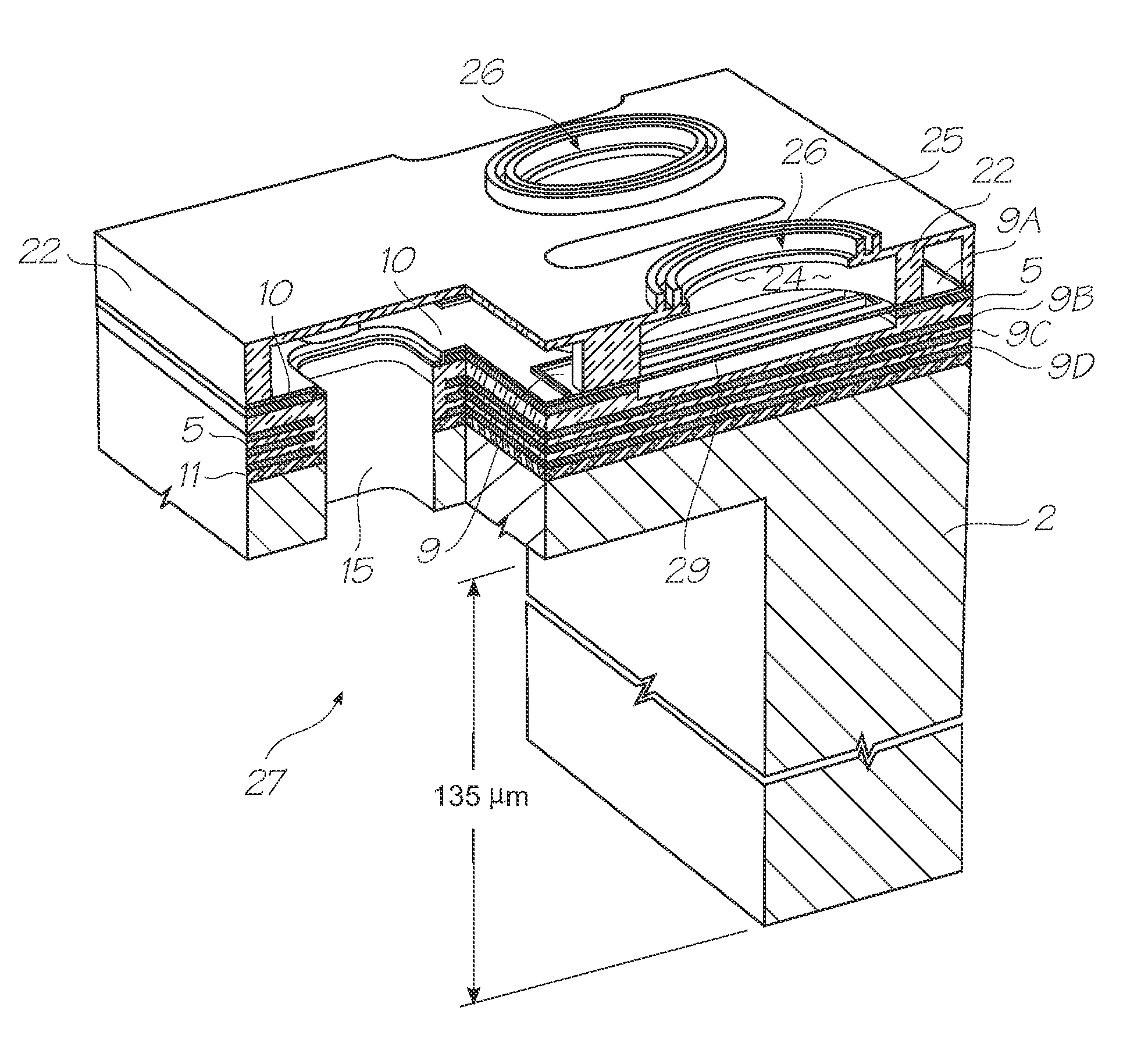
  • Inkjet printer having printhead and ink for minimizing corrosion of exposed corrodible structures within printhead
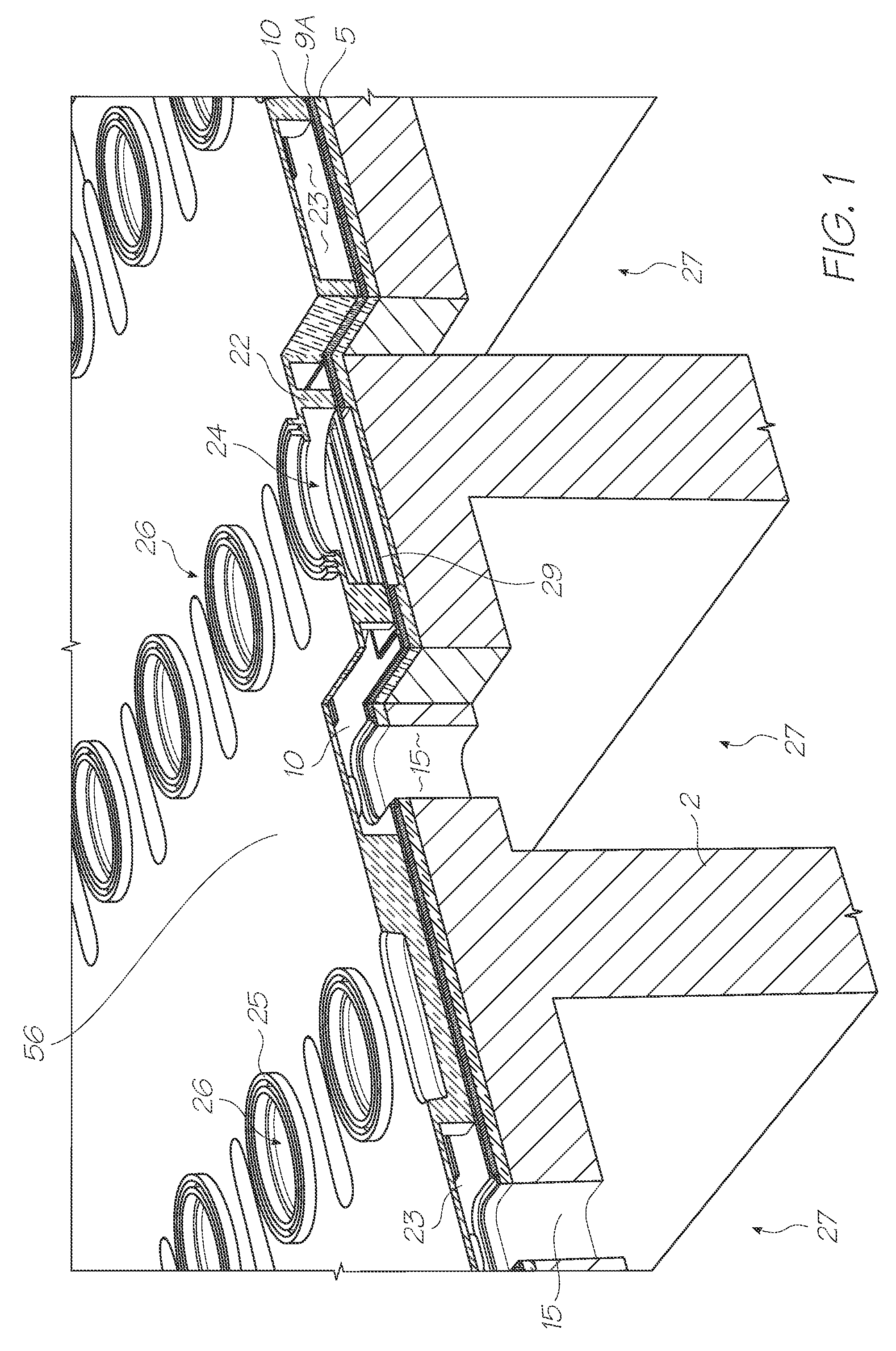
  • Inkjet printer having printhead and ink for minimizing corrosion of exposed corrodible structures within printhead
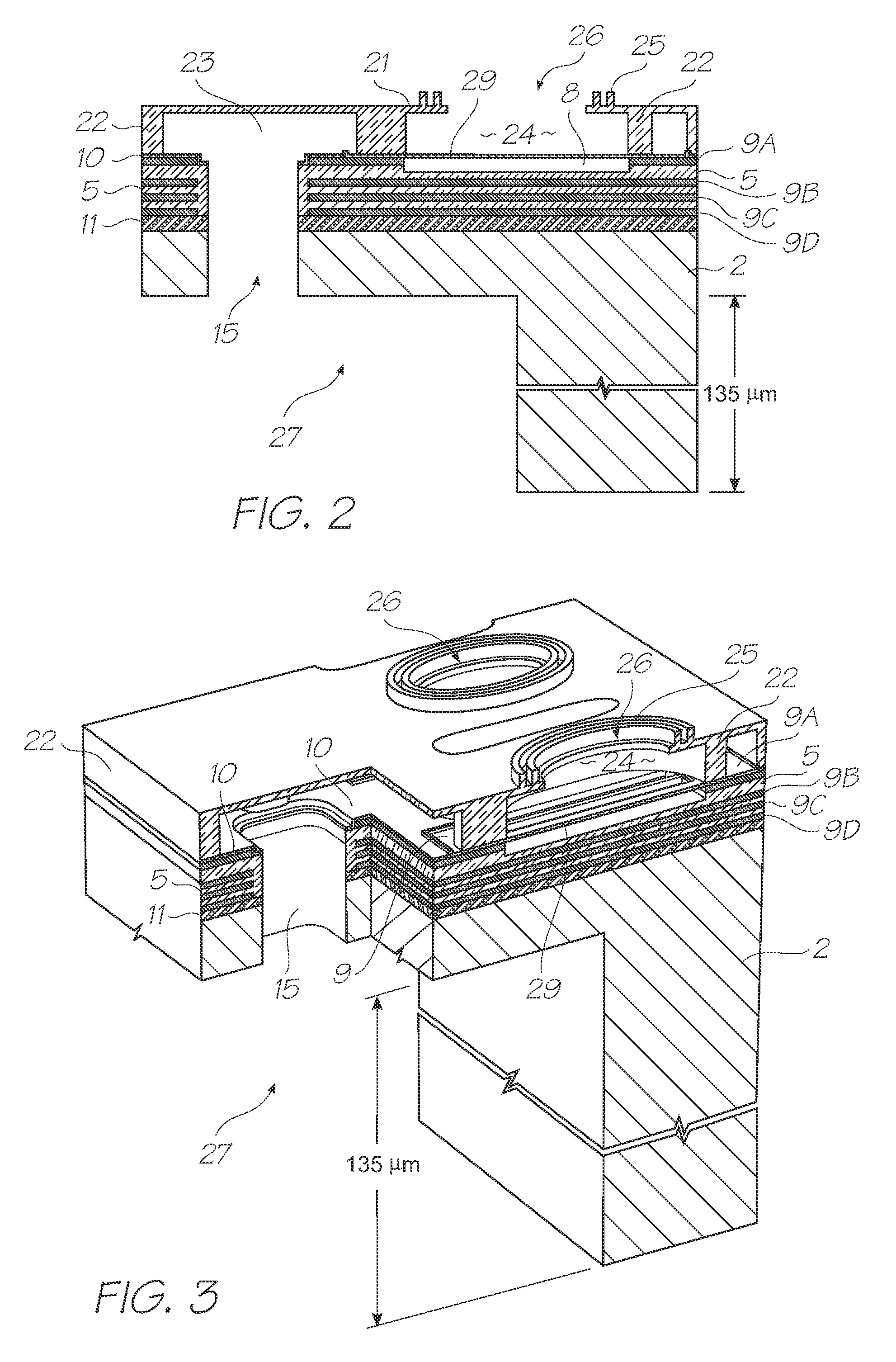
  • Inkjet printer having printhead and ink for minimizing corrosion of exposed corrodible structures within printhead

Examples


Embodiment Construction

[0106]As foreshadowed above, the present invention minimizes corrosion of corrodible structures in inkjet printheads which are exposed to certain dye-based inks. The corrodible structures are typically silicon nitride, BPSG and, to a lesser extent, silicon oxide.

Silicon Nitride Corrosion

[0107]Initially, the present Applicant observed print defects in certain color channels of its inkjet printheads, most noticeably in black color channels. Forensic examination of such printheads using SEM microscopy revealed that a degree of roof delamination was occurring and it was posited that the dye-based ink was responsible for corroding silicon nitride structures in the nozzle chamber. Significantly, in printheads having a bilayered roof (an upper layer of silicon oxide and a lower layer of silicon nitride), the corrosion was most evident in the silicon nitride layer. Silicon surfaces in the printhead were observed to be resistant to corrosion by the dye-based inks.

[0108]Following these observ...


PUM


Abstract

An inkjet printer includes: an inkjet printhead having an exposed corrodible structure containing silicon nitride, borophosphosilicate glass (BPSG) or silicon oxide; and an ink reservoir containing said ink which is in fluid communication with said printhead. The ink includes: water; a dye; and a metal additive for minimizing corrosion of the exposed structure.

Description

FIELD OF THE INVENTION[0001]This invention relates to inkjet inks for inkjet printers. It has been developed primarily for minimizing corrosion of corrodible structures in printheads by dye-based inkjet inks.CROSS REFERENCES[0002]The following patents or patent applications filed by the applicant or assignee of the present invention are hereby incorporated by cross-reference.[0003]6,755,5097,222,9437,188,4197,168,1667,086,71912 / 246,33212 / 246,3367,246,8867,128,4007,108,3556,991,3227,287,8367,118,19710 / 728,7847,364,2697,077,4936,962,40210 / 728,8037,147,30810 / 728,7797,118,1987,168,7907,172,2707,229,1556,830,3187,195,3427,175,2617,465,0357,108,3567,118,20210 / 773,1867,134,7447,134,7437,182,4397,210,7687,465,0367,134,7457,156,4847,118,2017,111,9267,431,4337,401,9017,468,13911 / 744,88511 / 097,3087,328,9787,334,8767,147,3067,448,7347,425,05011 / 014,76411 / 014,7637,331,6637,360,8617,328,9737,427,1217,407,2627,303,2527,249,82211 / 014,7627,311,3827,360,8607,364,2577,390,0757,350,8967,429,0967,384,13...

Claims


Application Information

Patent Timeline
Patent Type & Authority Patents(United States)
IPC IPC(8): G01D11/00B41J2/05
CPCC09D11/38C09D11/328B41J2202/03C09D11/40B41J2/14016C09D11/033
Inventor FIELDER, SIMONGIMONA, MICHELEDIGWEED, KATJA JOHANNACHANNARAYAPATNA, LAKSHMI
Owner MEMJET TECH LTD
Why Eureka
Eureka Blog
Learn More