

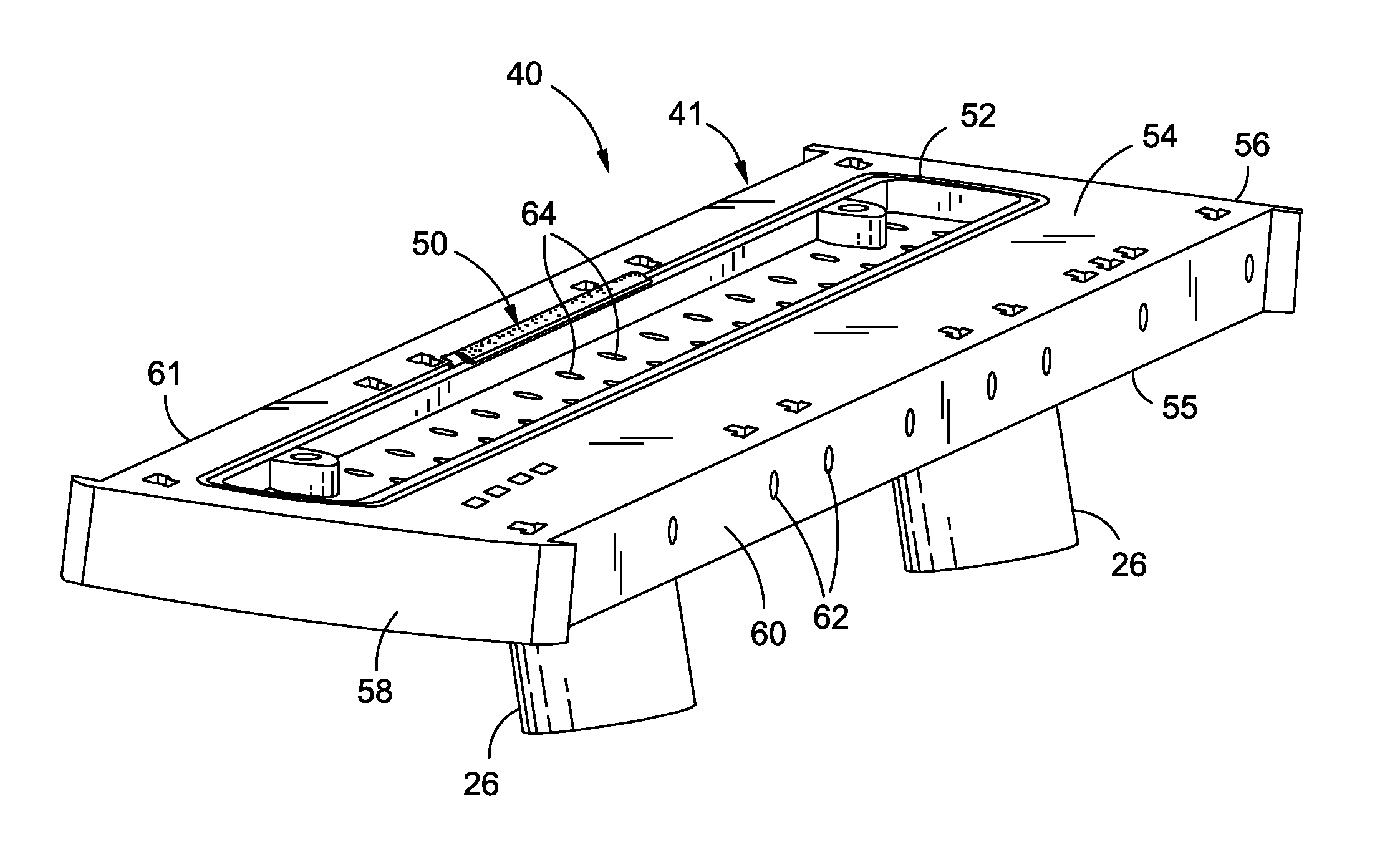
Drill template tool with integral seal
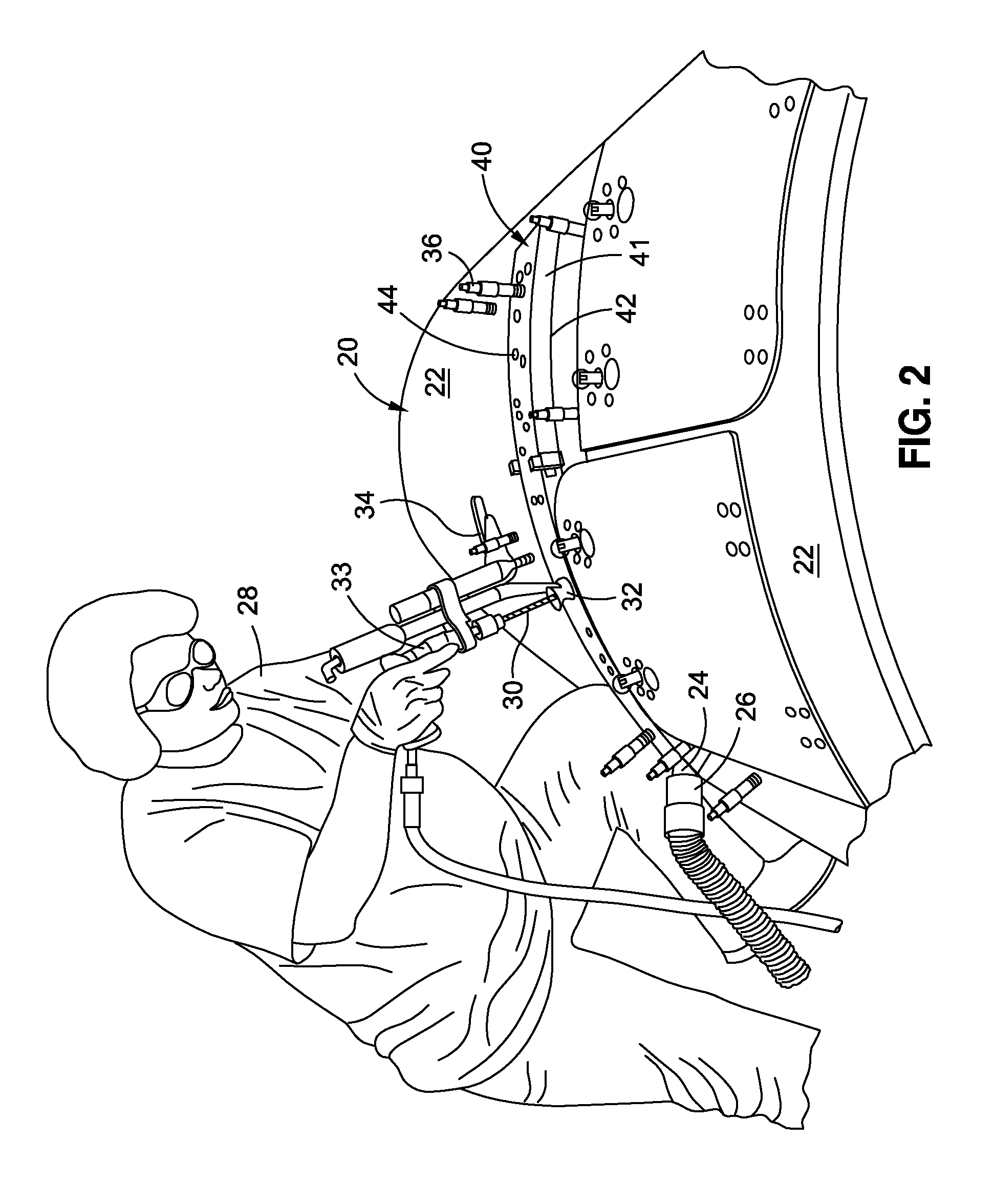
a drilling template and integral seal technology, applied in the field of drilling template tools, can solve the problems of increasing labor costs, affecting the work the known drill template tools do not include an integral seal to contain fluids and debris, so as to improve the working environment of drill operators, reduce cleaning time, and save labor costs
- Summary
- Abstract
- Description
- Claims
- Application Information
AI Technical Summary
Benefits of technology
Problems solved by technology
Method used
Image

Examples
Embodiment Construction
[0020]Disclosed embodiments will now be described more fully hereinafter with reference to the accompanying drawings, in which some, but not all of the disclosed embodiments are shown. Indeed, several different embodiments may be provided and should not be construed as limited to the embodiments set forth herein. Rather, these embodiments are provided so that this disclosure will be thorough and complete and will fully convey the scope of the disclosure to those skilled in the art.
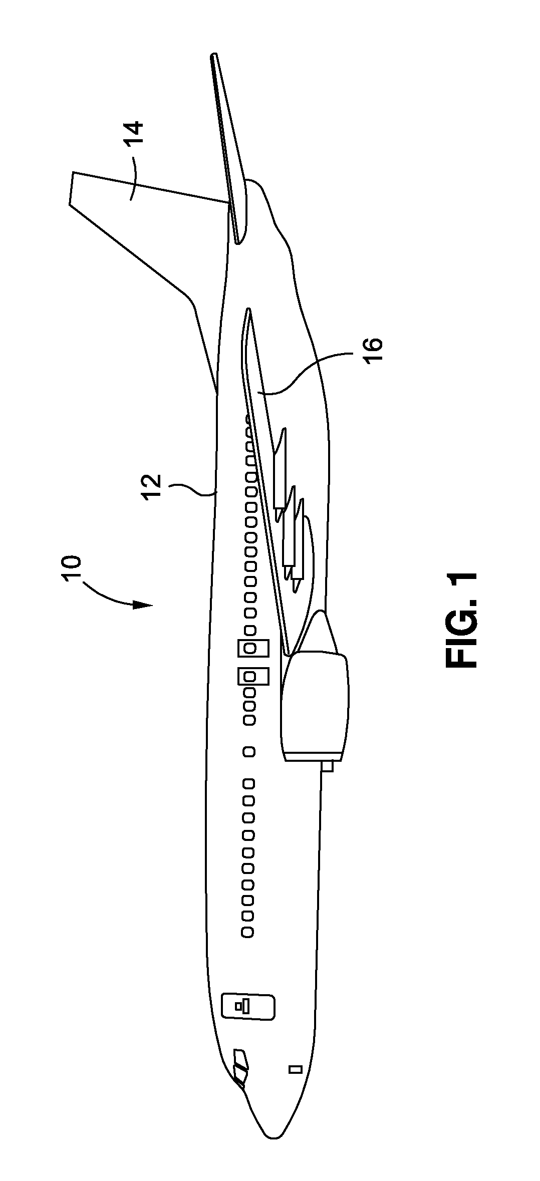
[0021]The disclosure provides for an improved drill template tool with integral seal. The improved drill template tool with integral seal device of the disclosed embodiments may be used to manufacture composite and metallic parts for use on aircraft, spacecraft, watercraft, and other vehicles and craft. Accordingly, one of ordinary skill in the art will recognize and appreciate that the improved drill template tool with integral seal device of the disclosure can be used in any number of applications involv...
PUM
| Property | Measurement | Unit |
|---|---|---|
| Pressure | aaaaa | aaaaa |
Abstract
Description
Claims
Application Information