Electrical power distribution

a technology of electric power distribution and power distribution circuit, which is applied in non-electric variable control, process and machine control, instruments, etc., can solve the problems of increasing the potential for unpredictable faults and system size expansion, and achieves easy expansion of power supply system, less wiring, and high availability

Active Publication Date: 2014-06-24
GE AVIATION SYST LTD
View PDF25 Cites 13 Cited by
  • Summary
  • Abstract
  • Description
  • Claims
  • Application Information

AI Technical Summary

Benefits of technology

[0013]By providing a distributed control system architecture, and methods, for a power supply in accordance with various aspects of the present invention, a power supply system having high availability and reliability can be provided. Such a power supply system is particularly suited to use in safety-critical applications, such as, for example, in aerospace power distribution systems.
[0014]Additionally, various embodiments of the present invention provide a simple, modular architecture. This makes expansion of the power supply system easy, without the need to add multiple extra connecting wires and without complicating the system architecture to the point where unintended non-predictable faults (e.g. caused by instruction conflicts / timing errors / etc.) may occur.
[0015]As an added bonus, certain embodiments of the present invention can be made to be physically lighter and more compact than for conventional power supply systems, since they require less wiring; this being of particular benefit for weight and space constrained applications, such as, for example, aerospace.

Problems solved by technology

However, for certain applications, reliable continuous operation of various of the electrical loads may be critical to safety.
Nevertheless, whilst such power supply networks provide an improvement on previous conventional power supplies, there still exist various drawbacks associated with such networks.
For example, these networks tend to require complex controller architecture that not only makes such systems difficult to scale up in size, particularly when electrical contactors need to be distributed around an airframe for example, but that also increases the potential for unpredictable faults to occur.

Method used


Image

  • Electrical power distribution
  • Electrical power distribution
  • Electrical power distribution

Examples


Embodiment Construction

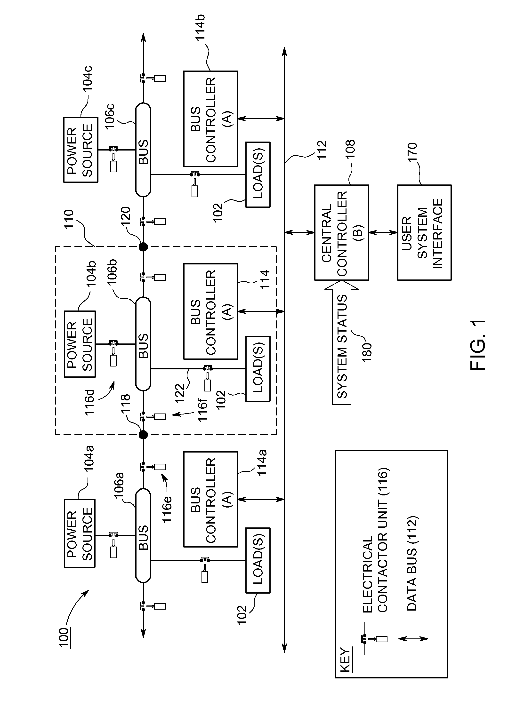
[0021]FIG. 1 shows a power supply system 100 according to an embodiment of the present invention. The power supply system 100 may be used for power distribution to one or more loads 102 in a safety-critical power supply network, such as that found, for example, in various aircraft.

[0022]The power supply system 100 comprises at least one power source 104, a power bus 106, and a distributed control system. The distributed control system comprises a central controller 108 that is operably coupled to at least one bus module 110 through a data bus 112. The bus module(s) 110 each comprise a respective bus controller 114 that is operable to connect a respective power source 104 to the power bus 106.

[0023]The power supply system 100 may be used to support a number of individually powered loads for a user system (not shown). The user system can be connected to the power supply system 100 through a user system interface 170. The user interface 170 enables the user to see the high level config...


PUM


Abstract

The present invention relates generally to electrical power distribution, for example, in aircraft. More particularly, according to a first aspect, the present invention relates to a power supply system for power distribution to one or more loads in a safety-critical power supply network. The power supply system comprises at least one power source, a power bus and a distributed control system. The distributed control system comprises a central controller operably coupled to at least one bus module through a data bus. Bus modules include bus controllers that are operable to connect respective power sources to the power bus.

Description

CROSS-REFERENCE TO RELATED APPLICATIONS[0001]This application claims priority under 35 U.S.C. §119(a)-(d) or (f) to prior-filed, co-pending British application number 0904487.6, filed on Mar. 16, 2009, which is hereby incorporated by reference in its entirety.BACKGROUND OF THE INVENTION[0002]1. Field of the Invention[0003]The present invention relates generally to electrical power distribution. More particularly, the present invention relates to a power supply system and method for power distribution in a safety-critical power supply network, such as might be provided, for example, in certain aircraft.[0004]2. Description of the Related Art[0005]It is generally well-known to provide power supply networks to distribute power from various power sources to various electrical loads that consume the distributed electrical power [1-4].[0006]However, for certain applications, reliable continuous operation of various of the electrical loads may be critical to safety. For example, in an airc...

Claims


Application Information

Patent Timeline
Patent Type & Authority Patents(United States)
IPC IPC(8): H02J1/00
CPCH02J3/18H02J3/14Y10T307/25Y10T307/461H02J13/0079H02J4/00H02J13/0062Y10T307/313H02J2310/44H02J13/00016H02J13/00028Y04S20/222Y02B70/3225H02J3/38
Inventor WEALE, DENIS, VAUGHAN
Owner GE AVIATION SYST LTD
Why Eureka
Try Eureka