LED light string color mixing and synchronization circuit

a technology of color mixing and synchronization circuit, which is applied in the direction of instruments, lighting support devices, coupling device connections, etc., can solve the problems of increasing the cost of ic in each light, wasting cost, and not being able to synchronize the color change, so as to reduce the number of ic control chips used, the effect of simple structur

Inactive Publication Date: 2014-06-24
PENG MEI LING
View PDF6 Cites 1 Cited by
  • Summary
  • Abstract
  • Description
  • Claims
  • Application Information

AI Technical Summary

Benefits of technology

[0004]The technical solution adopted in the present invention is that each of LED lights composed of an LED light string comprises two input terminals and two output terminals, wherein the two input terminals are respectively an input terminal of reverse parallel connection of any two of three primary light-emitting chips of R, G, B and an anode input terminal of the remaining primary light-emitting chip and the two output terminals are respectively an output terminal of reverse parallel connection of any two of three primary light-emitting chips of R, G, B and a cathode output terminal of the remaining primary light-emitting chip. Thus, each of the LED lights of the LED light suing is connected in a two-input two-output series connection to form a light string arrangement with two terminals thereof in combination with four electrical wires. The advantage of the present invention is that the structure is simple and connection of a group of LED lights in series for proper operation can be realized through a minimum number of connection wires with modification being only made on electrical connection among the three primary light-emitting chips of R, G, B so as to reduce the number of IC control chips used and achieve synchronous color change of the light-emitting chips
[0005]The advantage of the present invention is that the structure is simple and connection of a group of LED lights in series for proper operation can be realized through a minimum number of connection wires with modification being only made on electrical connection among the three primary light-emitting chips of R, G, B so as to reduce the number of IC control chips used and achieve synchronous color change of the light-emitting chips.

Problems solved by technology

The shortcomings are that (1) the electrical current of the light string is large, making it not possible to make a light string of a large number of lights; (2) no high voltage can be applied; and (3) eight wires are needed for the light string, generally leading to a waste of cost.
A light string of this way is not capable of synchronous change of color and the inclusion of an IC in each light also increases the cost.
In this way, the volume and weight of the light string are both increased and the manufacturing cost is also increased.

Method used


Image

  • LED light string color mixing and synchronization circuit
  • LED light string color mixing and synchronization circuit
  • LED light string color mixing and synchronization circuit

Examples


first embodiment

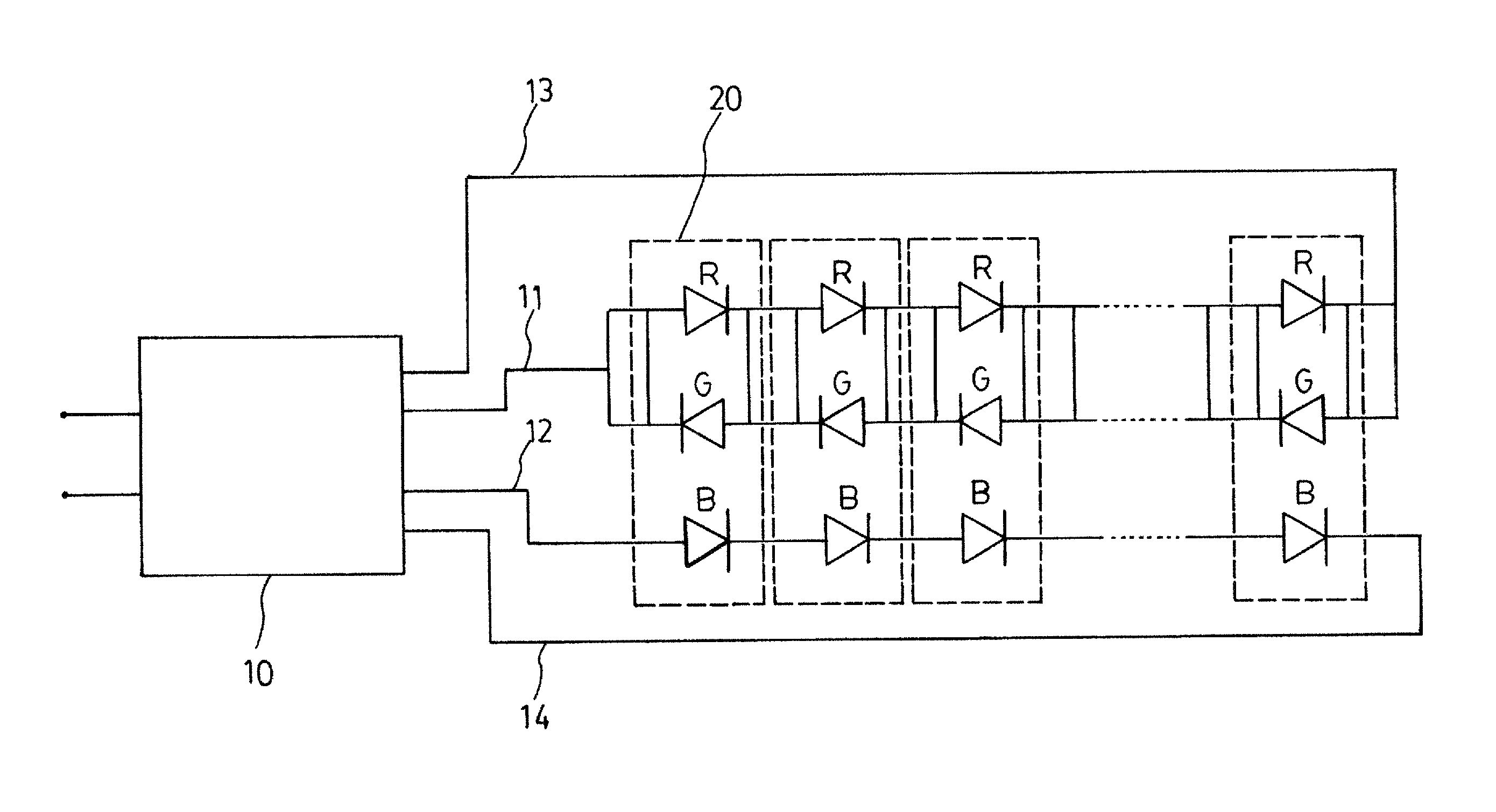
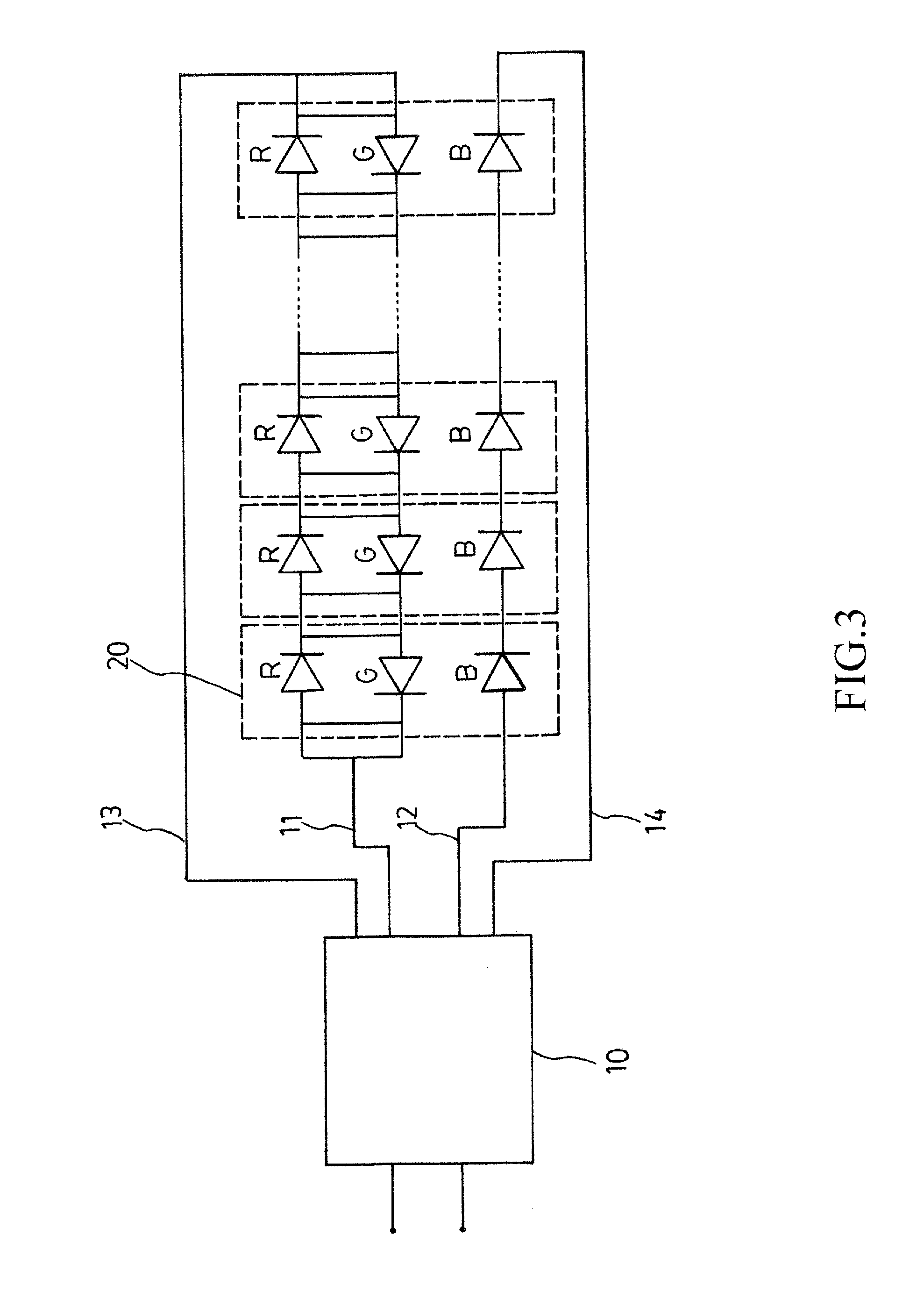
[0018]Referring to FIG. 3, in an LED light string according to the present invention, the connection arrangement of the three primary light-emitting chips of R, G, B of each LED light (20) is such that the two input terminals are respectively an input terminal of parallel connection of an anode of an R primary light-emitting chip and a cathode of a G primary light-emitting chip and an anode input terminal of a B primary light-emitting chip and the two output terminals are respectively an output terminal of parallel connection of a cathode of the R primary light-emitting chip and an anode of the G primary light-emitting chip and a cathode input terminal of the B primary light-emitting chip. The LED light string is controlled by a controller (10) that is provided with four electrical wires (11), (12), (13), (14), among which the electrical wires (11), (12) each have one end connected to the controller (10) and an opposite end connected to an input of the electrical connection of the L...

second embodiment

[0019]Referring to FIG. 4, in an LED light string according to the present invention, the connection arrangement of the three primary light-emitting chips of R, G, B of each LED light (20) is such that the two input terminals are respectively an input terminal of parallel connection of an anode of an R primary light-emitting chip and a cathode of a B primary light-emitting chip and an anode input terminal of a G primary light-emitting chip and the two output terminals are respectively an output terminal of parallel connection of a cathode of the R primary light-emitting chip and an anode of the B primary light-emitting chip and a cathode input terminal of the G primary light-emitting chip. The LED light string is controlled by a controller (10) that is provided with four electrical wires (11), (12), (13), (14), among which the electrical wires (11), (12) each have one end connected to the controller (10) and an opposite end connected to an input of the electrical connection of the L...

third embodiment

[0020]Referring to FIG. 5, in an LED light string according to the present invention, the connection arrangement of the three primary light-emitting chips of R, G, B of each LED light (20) is such that the two input terminals are respectively an input terminal of parallel connection of an anode of a G primary light-emitting chip and a cathode of a B primary light-emitting chip and an anode input terminal of an R primary light-emitting chip and the two output terminals are respectively an output terminal of parallel connection of a cathode of the G primary light-emitting chip and an anode of the B primary light-emitting chip and a cathode input terminal of the R primary light-emitting chip. The LED light string is controlled by a controller (10) that is provided with four electrical wires (11), (12), (13), (14), among which the electrical wires (11), (12) each have one end connected to the controller (10) and an opposite end connected to an input of the electrical connection of the L...


PUM


Abstract

The present invention provides an LED light string color mixing and synchronization circuit, in which each of LED lights composed of an LED light string includes two input terminals and two output terminals. The two input terminals are respectively an input terminal of reverse parallel connection of any two of three primary light-emitting chips of R, G, B and an anode input terminal of the remaining primary light-emitting chip and the two output terminals are respectively an output terminal of reverse parallel connection of any two of three primary light-emitting chips of R, G, B and a cathode output terminal of the remaining primary light-emitting chip. Thus, each of the LED lights of the LED light string is connected in a two-input two-output series connection to form a light string arrangement with two terminals thereof in combination with four electrical wires.

Description

TECHNICAL FIELD OF THE INVENTION[0001]The present invention generally relates to an LED light string color mixing and synchronization circuit, and more particularly to electrical connection of three primary color light-emitting chips of R, G, B of each LED light of the LED light string that allows LED lights to be connected in series to form an LED light string.DESCRIPTION OF THE PRIOR ART[0002]In the known technology of light string composed of LED lights comprising color light-emitting chips, electrical connection of the three primary color light-emitting chips of R, G, B of each LED light in the LED light string is generally a parallel connection structure with a common cathode or a common anode and all the lights are connected in series when put in use. The shortcomings are that (1) the electrical current of the light string is large, making it not possible to make a light string of a large number of lights; (2) no high voltage can be applied; and (3) eight wires are needed for ...

Claims


Application Information

Patent Timeline
Patent Type & Authority Patents(United States)
IPC IPC(8): H05B37/00
CPCH05B37/00H05B33/0857H05B33/0821H05B45/40H05B45/20H05B45/42H05B45/18
Inventor PENG, MEI-LING
Owner PENG MEI LING
Why Eureka
Try Eureka