Corona ignition device

a technology of ignition device and corona, which is applied in the direction of combustion ignition, transformer/inductance casing, combustion process, etc., can solve the problems of ignition device failure prematurely, dielectric strength problem, insulation problem, etc., and achieve the effect of partial discharge, and significantly reducing the risk of voltage overload

Inactive Publication Date: 2014-07-01
BORGWARNER BERU SYST
View PDF11 Cites 4 Cited by
  • Summary
  • Abstract
  • Description
  • Claims
  • Application Information

AI Technical Summary

Benefits of technology

[0007]In operation of corona ignition devices with frequencies of typically at least 1 MHz and voltages of a few kV, the dielectric strength has proven problematic. Voltage overloads and partial discharges often cause the ignition device to fail prematurely. Within the scope of the invention it was found that the risk of voltage overloads can be significantly reduced by inserting a metal cap onto an end section of the bobbin facing the insulator. Such a metal cap provides electromagnetic shielding of the coil end and thereby reduces the risk of voltage overloads and partial discharges.
[0008]The metal cap preferably rests against at least one winding of the coil. The metal cap can cover a few windings of the coil or terminate upstream of the coil. It is therefore advantageous when the metal cap extends at least to, or even covers the coil end. Preferably the metal cap tapers toward the cap end facing away from the insulator, i.e. toward the coil. In this manner the field distribution at the end of the metal cap can be evened out further, thereby reducing the risk of voltage overloads.
[0009]Field peaks at the end of the coil, which can result in insulation problems, can also be reduced by tapering the coil toward the insulator. This can be reduced with minimal effort by winding the coil on a bobbin which comprises a section which tapers toward the insulator. Windings on the tapering section of the bobbin then have a diameter that becomes smaller the more closely the insulator is approached.
[0010]Field peaks at the coil end, which is at particular risk for voltage overloads, can be largely prevented by using a coil winding that tapers toward the insulator, i.e. by an outer diameter of the winding that decreases toward the insulator. An ignition device according to the invention therefore has a longer service life.
[0011]It is particularly advantageous to combine the two measures according to the invention, i.e. a coil tapering toward the insulator and a metal cap inserted onto the bobbin, since a particularly significant improvement can be achieved in this manner. Preferably, the metal cap covers a tapering section of the bobbin. The service life of the ignition device can be markedly improved by using only one of these two measures, however.

Problems solved by technology

In operation of corona ignition devices with frequencies of typically at least 1 MHz and voltages of a few kV, the dielectric strength has proven problematic.
Voltage overloads and partial discharges often cause the ignition device to fail prematurely.
Field peaks at the end of the coil, which can result in insulation problems, can also be reduced by tapering the coil toward the insulator.

Method used


Image

  • Corona ignition device
  • Corona ignition device

Examples


Embodiment Construction

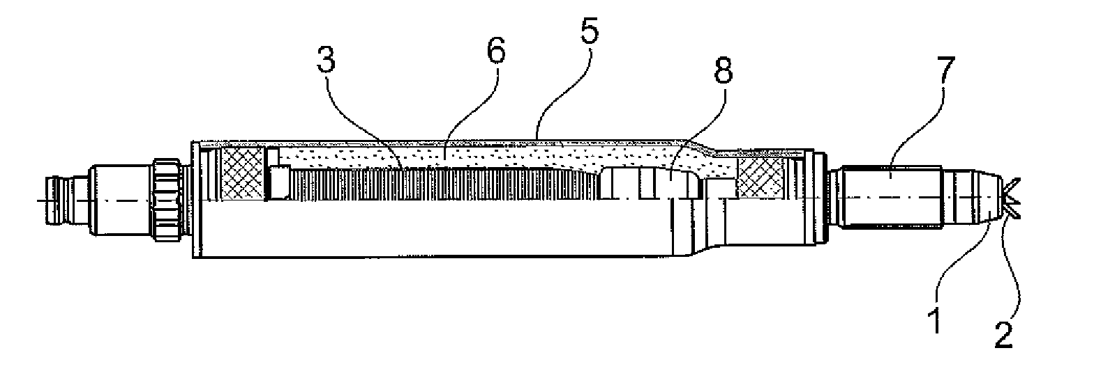
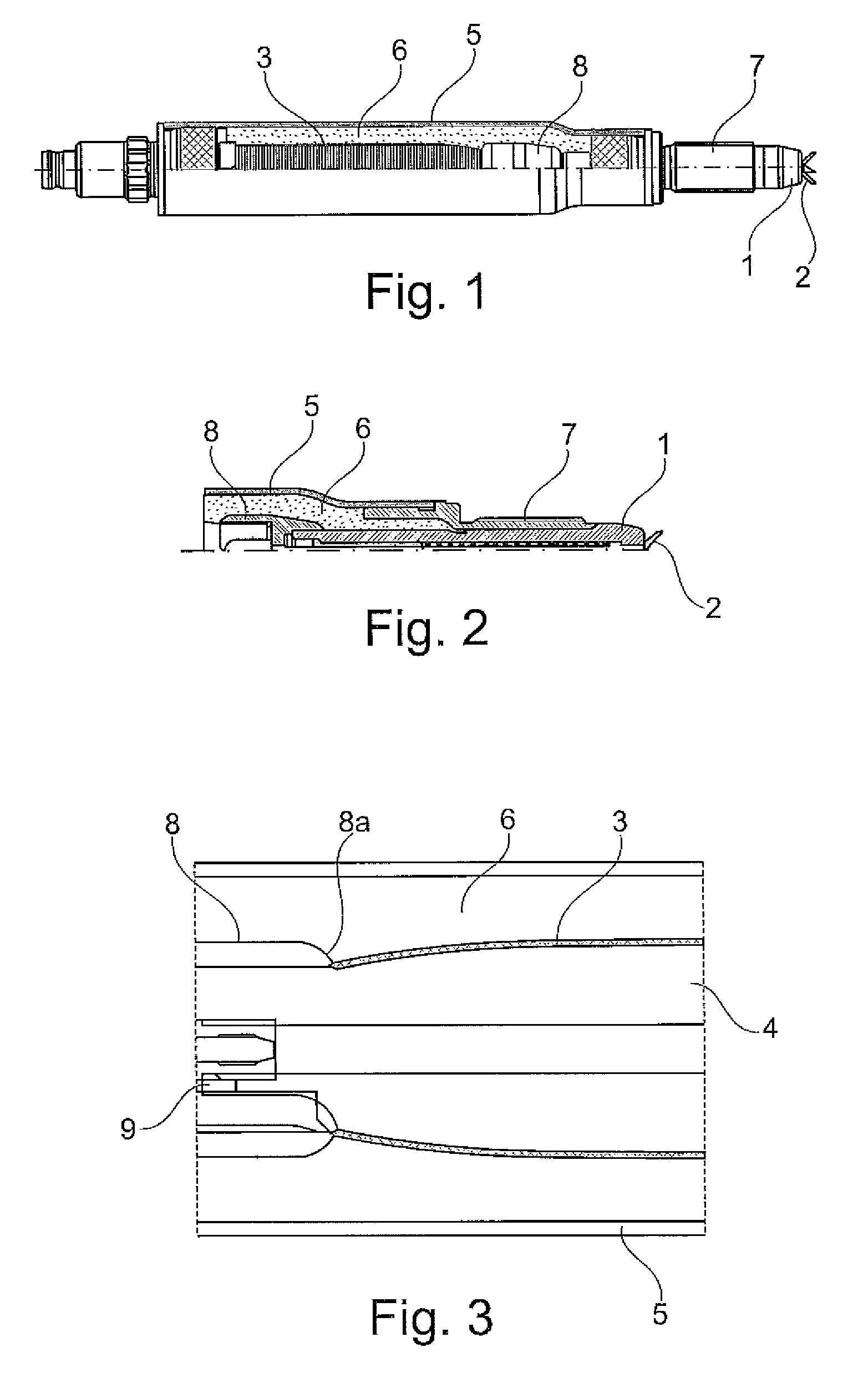
[0017]FIG. 1 shows, in a partially exposed view, an embodiment of an ignition device for igniting fuel in an internal combustion engine by producing a corona discharge. FIGS. 2 and 3 each show cross-sectional detailed views of the ignition device.

[0018]The ignition device comprises an insulator 1 which carries a center electrode 2. In the embodiment shown, the center electrode 2 comprises a plurality of ignition tips in order to produce a particularly large plasma volume and to thereby improve the ignition properties. Instead of a branched center electrode, it is also possible to use an unbranched center electrode, i.e. a simple pin.

[0019]The insulator 1 comprises a central bore through which the center electrode 2 is connected to a coil 3. The coil 3 is wound onto a bobbin 4 and is enclosed by a tube housing 5. The annular space between the coil 3 and the tube housing 5 is filled with insulating material6, e.g. casting compound, coating, or insulating oil.

[0020]The insulator 1 is e...


PUM

PropertyMeasurementUnit
resonance frequencyaaaaaaaaaa
frequenciesaaaaaaaaaa

Abstract

The invention relates to an ignition device for igniting fuel in an internal combustion engine by generating a corona discharge, comprising an insulator which carries a center electrode, a coil attached to the center electrode, the coil being wound onto a bobbin and enclosed by a tube housing. According to the invention, the coil tapers toward the insulator.

Description

[0001]The invention is directed to a corona ignition device. Such ignition devices are also referred to as HF ignition devices and are known from EP 1 515 594 A2, for example.[0002]A method for igniting fuel in a combustion chamber of an internal combustion engine by way of a corona discharge produced in the combustion chamber is also described in U.S. 2004 / 0129241 A1. A center electrode held by an insulator is used, which forms a capacitance together with an outer conductor enclosing the insulator or with the walls of the combustion chamber at ground potential, as counter electrode. The insulator enclosing the center electrode and the combustion chamber with the contents thereof act as a dielectric. Air or a fuel / air mixture or exhaust gas is located therein, depending on which stroke the piston is engaged in.[0003]This capacitance is a component of an electric oscillating circuit which is excited using a high-frequency voltage which is created, for example, using a transformer hav...

Claims


Application Information

Patent Timeline
Patent Type & Authority Patents(United States)
IPC IPC(8): F23Q3/00F02P17/00H01F27/02
CPCH01T13/44F23Q3/00H01T13/467H01T13/50H01T13/00F02P23/045F02P15/00
Inventor STIFEL, TIMOGIFFELS, THOMASMUELLER, AXEL
Owner BORGWARNER BERU SYST
Why Eureka
Try Eureka