Implantable subcutaneous device

a subcutaneous device and implantable technology, applied in the field of implantable subcutaneous devices, to achieve the effect of facilitating positioning, reducing the trauma of detachment of skin, and facilitating placemen

Active Publication Date: 2014-07-01
NEURELEC
View PDF15 Cites 15 Cited by
  • Summary
  • Abstract
  • Description
  • Claims
  • Application Information

AI Technical Summary

Benefits of technology

[0018]The present invention permits furthering the research for reducing the encumbrance of the implantable device with increasingly greater resistance, while having good and sufficient characteristics and transmission and electric recharge quality, while allowing the implanted magnetic to be extracted.
[0024]The result is a new, very compact, implantable subcutaneous device that can have a thickness of at least 5 mm for 30 mm of outer diameter and which limits both its outer surface and the dimensions of the part of the external device that faces it; its positioning is thus facilitated, also reducing the trauma of detaching the skin, and the implant makes fewer shadows during MRI or x-ray imaging; the implantable device also permits, according to the invention, placing the implant magnet nearest the skin, assuring a greater attraction with the external magnet, which permits reducing the strength of these magnets and thus their dimensions, and also reducing the overall size of the assembly of devices.
[0025]In addition, making the housing of ceramic offers greater shock resistance, both by the material and the shape of the hollow crown part forming the housing for the electronic part and the coil and which constitutes a U-shaped arch shorter than that of a disk-shaped housing.

Problems solved by technology

All these manufacturers have performed studies and made compromises in the design of their devices in order to simultaneously satisfy contradictory constraints such as: the necessity for the implants to be biocompatible, the simplest possible implementation for the surgeon, a minimum encumbrance, a sufficient yield both in data transmission and in electric recharging of the implant (low yield, in fact, as a result of the proximity of the receiving / transmitting antennas to the titanium housing, and the poor electromagnetic coupling of the coils for energy transfer), as well as the presence of magnets, which also disrupts MRI imaging, and in that one must be able to act on the body of the patient concerned.

Method used


Image

  • Implantable subcutaneous device
  • Implantable subcutaneous device
  • Implantable subcutaneous device

Examples


Embodiment Construction

)

[0032]The entire description of the figures below is only one example of embodiment referring to the principal application of the invention, which is to create auditory prostheses comprising an implantable subcutaneous device, but the device according to the invention can be used in other applications, each time that it is necessary or useful to be able to collect data on an organ by using, for example, so-called physiological data collection electrodes, or, in contrast, to send information to this organ (such as the cochlea, taken as an example below) from outside the living body without permanent perforation of the skin.

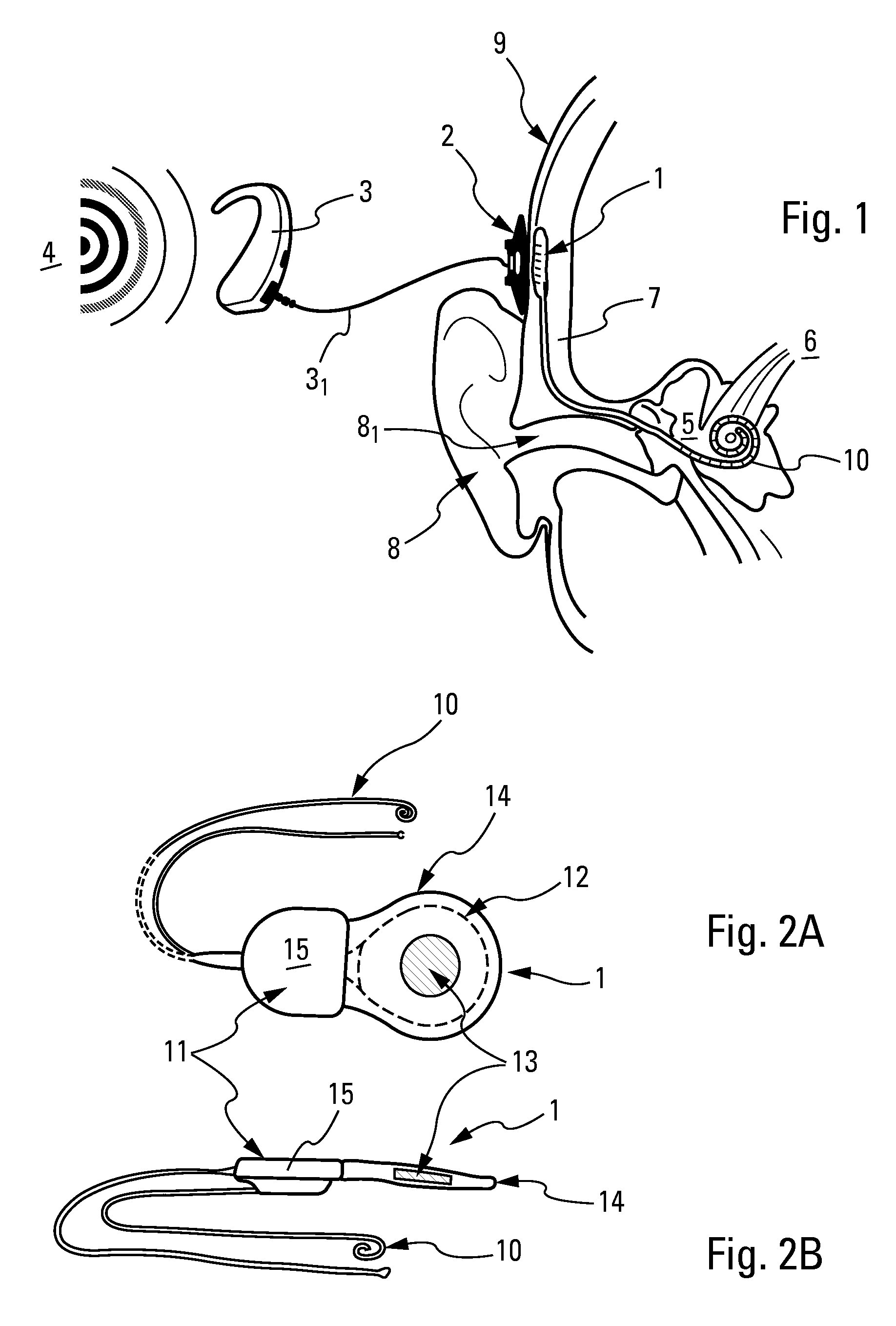
[0033]In the present example of auditory prostheses, such as shown in FIG. 1, sounds 4 are captured by a microphone situated on an outer housing 3, which also comprises a microprocessor to digitize and process the sound thus captured and which is, in general, a support of the behind-the-ear type for placing it discretely behind ear 8. In another embodiment, said o...


PUM


Abstract

Implantable subcutaneous device of biocompatible material that can receive data and energy by electromagnetic coupling with at least one external device is disclosed. The implantable device bears an airtight housing and a magnet that can hold the other external device centered with the implantable device. The housing bears a hollow crown containing at least electronic device(s) and a coil, and a bottom sealing the opening of the crown in an airtight manner. The magnet has dimensions compatible with a central housing formed by the so-called internal wall of the crown and in which it is positioned.

Description

BACKGROUND[0001](1) Field of the Invention[0002]The subject of the present invention is an implantable subcutaneous device that can be positioned anywhere in a living body, directly under the skin of this body to send and / or receive data to or from the outside of said body, such as to at least one other device positioned outside said body.[0003]One of the principal applications of this invention is to create auditory prostheses intended to correct profound deafness of a human being and that comprises electrodes for this purpose either implanted in the cochlea, or extracochlear and positioned on the round or oval window of the cochlea, and designed to send electrical signals to the auditory nerve fibers situated in this cochlea.[0004](2) Prior Art[0005]Such cochlear implants are known and thus replace deficient cochleas, directly stimulating the auditory nerve as a function of sound captured by an external microphone; this microphone is generally situated in a housing also comprising...

Claims


Application Information

Patent Timeline
Patent Type & Authority Patents(United States)
IPC IPC(8): A61N1/00
CPCA61N1/36032A61N1/375H04R2225/67A61N1/36038
Inventor CHARVIN, GUY
Owner NEURELEC
Why Eureka
Try Eureka