High accuracy heading sensor for an underwater towed array

Active Publication Date: 2014-07-01
THE UNITED STATES OF AMERICA AS REPRESENTED BY THE SECRETARY OF THE NAVY
View PDF1 Cites 32 Cited by
  • Summary
  • Abstract
  • Description
  • Claims
  • Application Information

AI Technical Summary

Benefits of technology

[0008]It is a general purpose and object of the present invention to provide a heading sensor that provides accurate heading measurements when the array is under dynamic motion, for example during vessel turns and during times of vessel straight course when the array is exhibiting unstable motion.
[000

Problems solved by technology

Existing heading sensors use fluxgate floating ring-core gimbal magnetometers that suffer significantly from reliability and production problems.
Due to the gimbal design of these sensors, the headin

Method used


Image

  • High accuracy heading sensor for an underwater towed array
  • High accuracy heading sensor for an underwater towed array
  • High accuracy heading sensor for an underwater towed array

Examples


Embodiment Construction

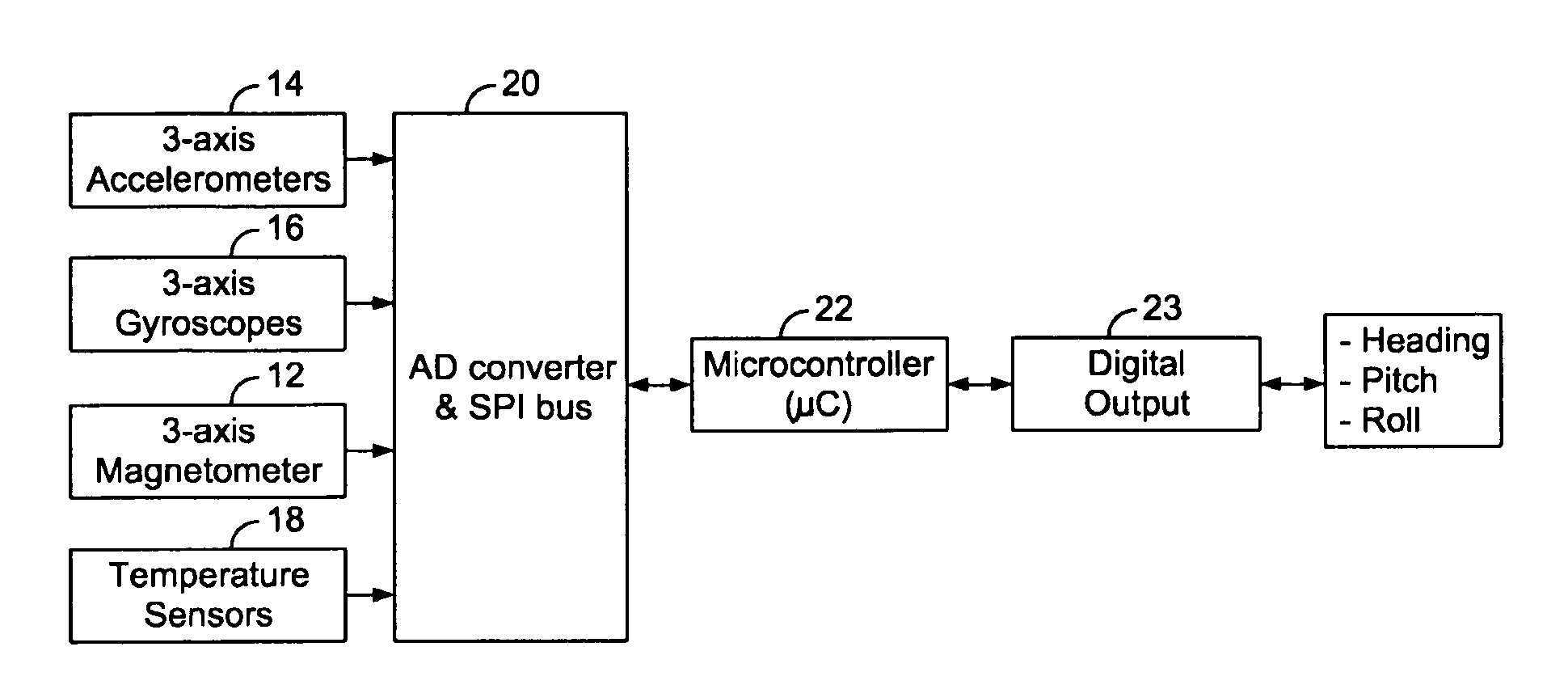
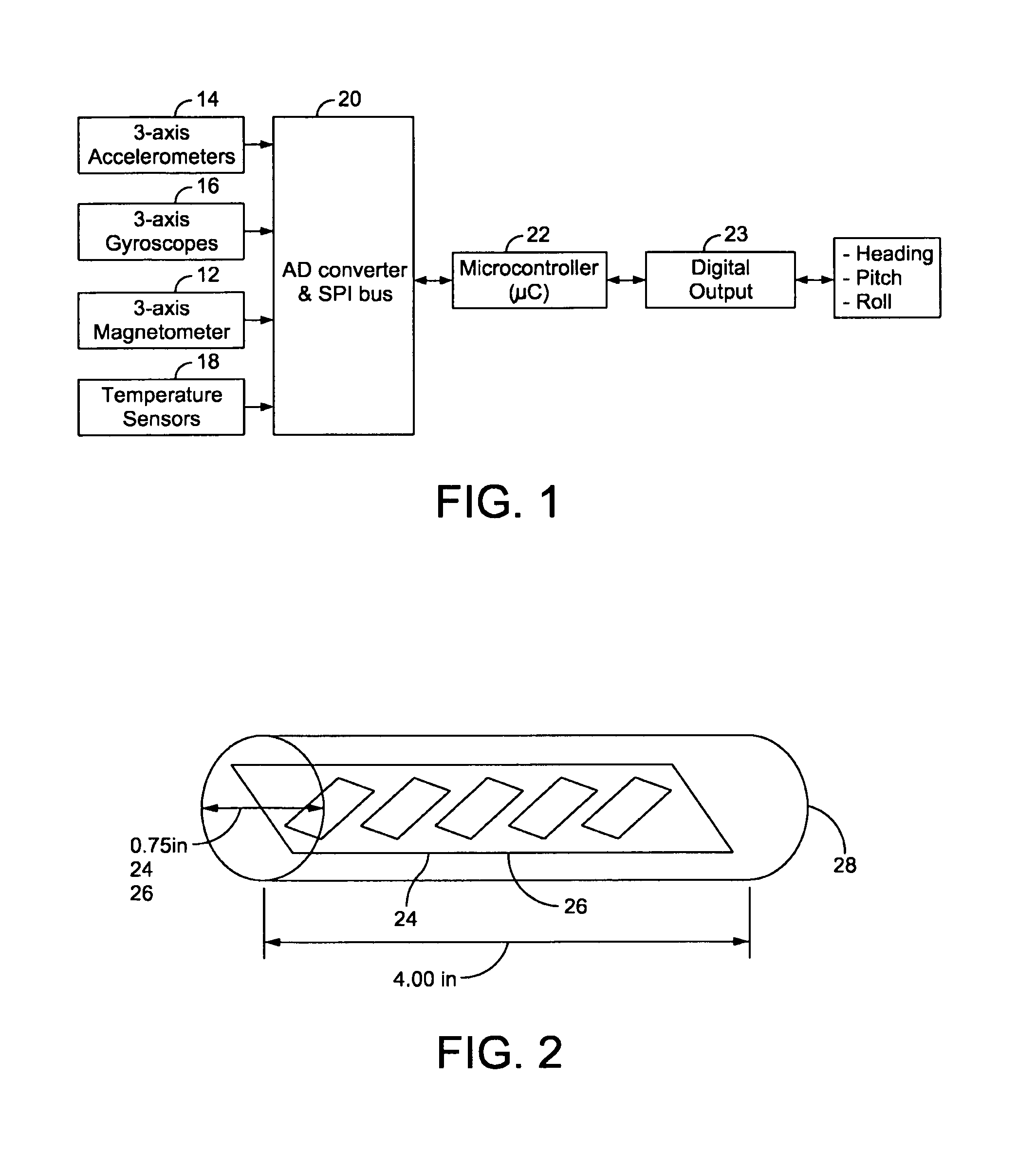
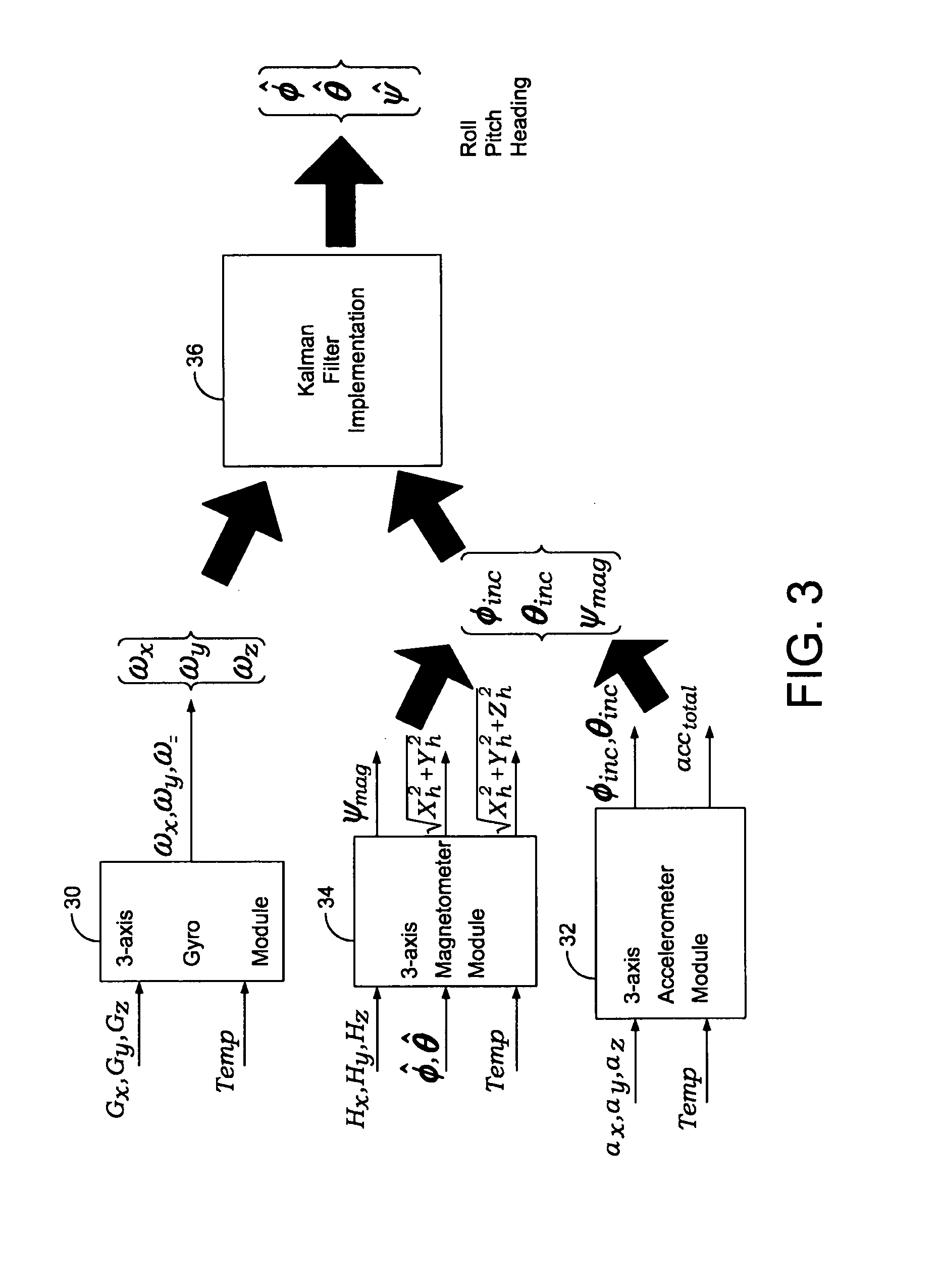
[0015]Referring now to FIG. 1 there is illustrated a heading sensor 10 for a towed array comprised of a suite of micro electro-mechanical system (MEMS) sensors and other miniature sensors. The heading sensor 10 fuses the output of individual sensors including accelerometers, gyroscopes and magnetometers to determine sensor heading, pitch and roll angles relative to the Earth's gravity vector and the horizontal component of the Earth's magnetic field vector.

[0016]The suite of micro electro-mechanical systems sensors and other miniature sensors comprises three magnetometers 12 (magneto-resistive or magneto-inductive) with each magnetometer 12 assigned to one of the three (x, y, z) spatial axes, three accelerometers 14 with each accelerometer 14 assigned to one of the three (x, y, z) spatial axes, three solid state MEMS gyroscopes 16 with each gyroscope 16 assigned to one of the three (x, y, z) spatial axes and a temperature sensor 18 for use in calibration of the other sensors. The an...


PUM


Abstract

A high performance solid-state heading sensor for underwater towed arrays is taught that combines high quality MEMS sensor components with data processing filters to resolve performance limitations present in prior art heading sensors. The heading sensor employs rate gyroscopes, accelerometers, magnetometers and a customized Kalman filter formulation implemented on a micro-controller to improve performance in determining the roll, pitch and heading of a towed array.

Description

STATEMENT OF GOVERNMENT INTEREST[0001]The invention described herein may be manufactured and used by or for the Government of the United States of America for governmental purposes without the payment of any royalties thereon or therefore.CROSS REFERENCE TO OTHER RELATED APPLICATIONS[0002]Not applicable.BACKGROUND OF THE INVENTION[0003](1) Field of the Invention[0004]The present invention relates to heading sensors for underwater towed arrays, and in particular to a high performance solid state heading sensor operated in conjunction with a data processing orientation formulation for towed acoustic arrays.[0005](2) Description of the Prior Art[0006]Current towed acoustic sonar arrays use magnetic heading sensors to measure the shape of the array to determine the azimuthal bearing of acoustic sources of interest and to allow for the determination of array shape for improved beamforming performance. The towed array application requires very high accuracy measurement of the horizontal a...

Claims


Application Information

Patent Timeline
IPC IPC(8): G01C21/16
CPCG01C21/16G01C21/183
Inventor ZAKI, AHMED S.STRAW, TIMOTHY B.OBARA, MICHAEL J.CHILD, PETER A.
Owner THE UNITED STATES OF AMERICA AS REPRESENTED BY THE SECRETARY OF THE NAVY
Why Eureka
Try Eureka