Method of lifting nacelle, nacelle lifting mechanism, tower, and wind turbine generator

a technology of nacelle and nacelle, which is applied in the direction of machines/engines, manufacturing tools, and final product manufacturing, etc., can solve the problems of many equipment and materials and people, the above-mentioned maintenance procedure, and the need for legal preparation, so as to achieve a small work amount

Active Publication Date: 2014-07-08
MITSUBISHI HEAVY IND LTD
View PDF18 Cites 8 Cited by
  • Summary
  • Abstract
  • Description
  • Claims
  • Application Information

AI Technical Summary

Benefits of technology

[0008]Therefore, an object of the present invention is to provide a technique for a maintenance work of separating a nacelle and a tower carried out at a little work amount without using a large crane.
[0018]According to the present invention, the maintenance work to separate a nacelle and the tower becomes able to be implemented without using a large-sized crane with the smaller work amount.

Problems solved by technology

However, there are two problems in the procedure of the above maintenance work.
The first problem lies in the necessity of many equipment and materials and persons and the necessity of legal preparations (for example, acquisition of a road use permission and the like).
This implies that a large expense and a long time period are required for the maintenance work.
The second problem lies in the necessity of a wide site in which the nacelle and a wind turbine rotor are located.
This decreases the freedom of the maintenance work.
However, a work for attaching the reception stage at the vicinity of the top end of the tower is not always easy.
For example, when the reception stage is attached to the tower by welding, a work time becomes long for the difficulty of the welding work at a high location.
Also, as disclosed in the above reference, a method of tapping a tower top flange to form a female screw and then engaging a bolt with the female screw to attach the reception stage requires a long work time.

Method used


Image

  • Method of lifting nacelle, nacelle lifting mechanism, tower, and wind turbine generator
  • Method of lifting nacelle, nacelle lifting mechanism, tower, and wind turbine generator
  • Method of lifting nacelle, nacelle lifting mechanism, tower, and wind turbine generator

Examples


Embodiment Construction

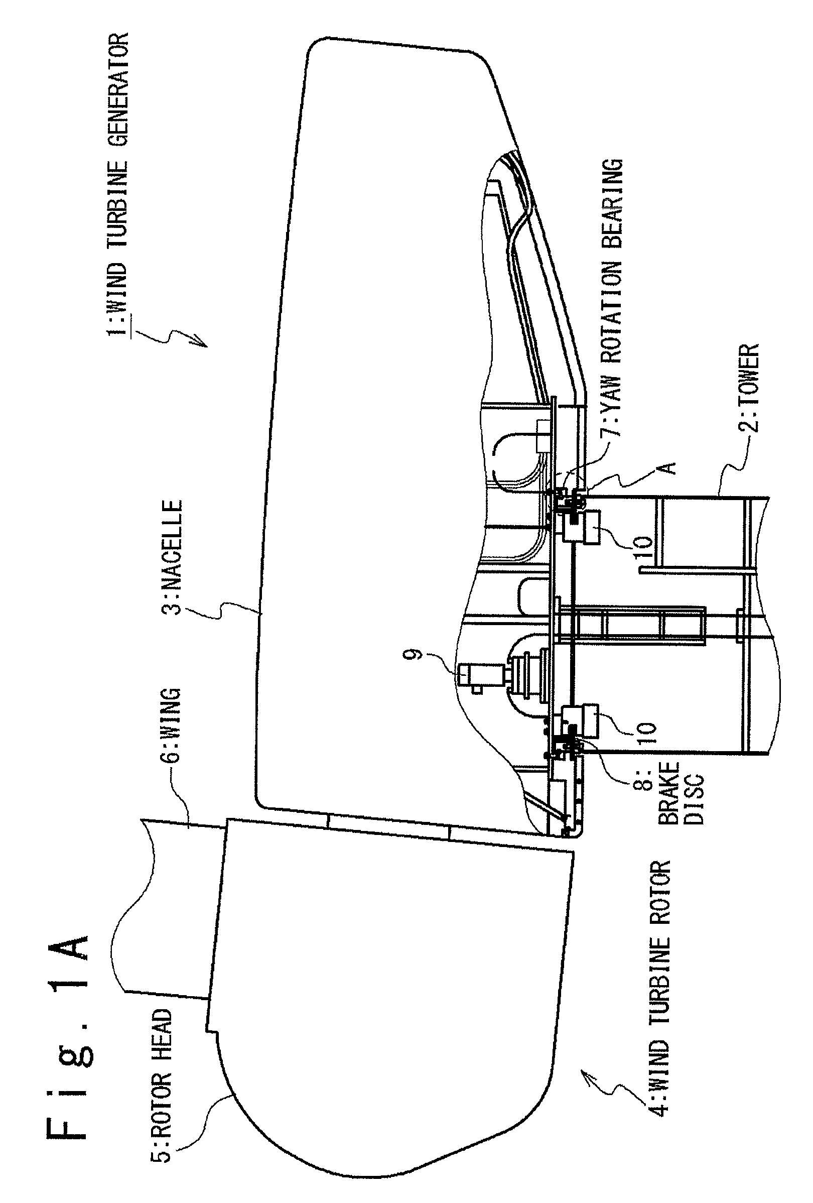
[0040]FIG. 1A is a partially sectional view showing a structure of a wind turbine generator to which a maintenance method according to an embodiment of the present invention is applied. At first, the outline of the configuration of a wind turbine generator 1 will be described. The wind turbine generator 1 contains a tower 2, a nacelle 3 provided on the tower 2, and a wind turbine rotor 4 that is rotatably attached to the nacelle 3. The wind turbine rotor 4 contains a rotor head 5 and wings 6. Although FIG. 1A shows only one wing 6, a plurality of wings 6 (typically, three wings 6) are actually attached to the rotor head 5.

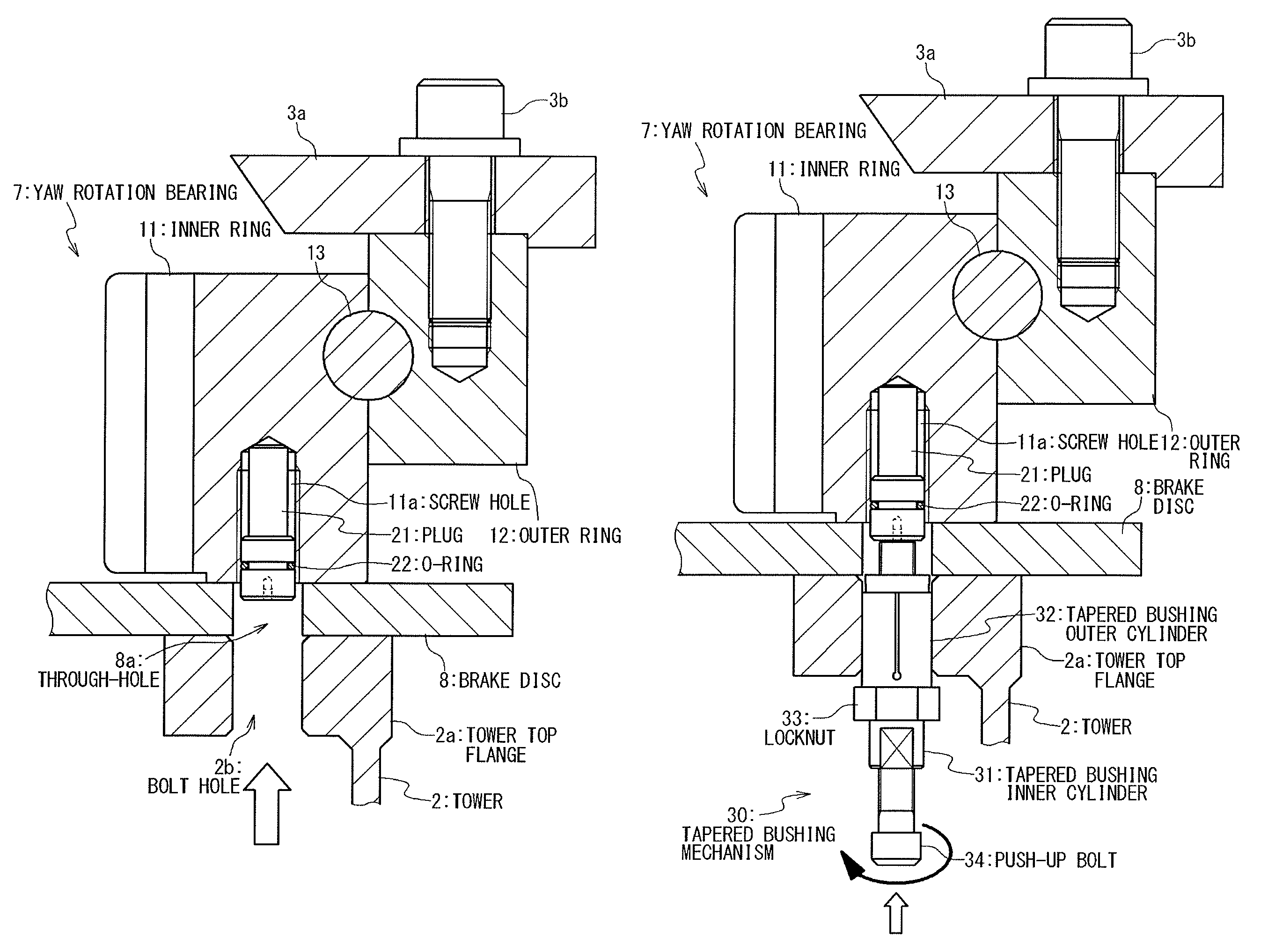
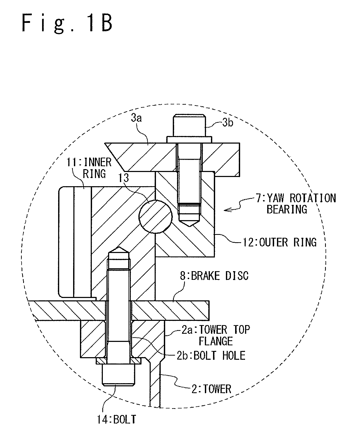
[0041]A yaw rotation bearing 7 is provided between the nacelle 3 and the tower 2. The nacelle 3 is rotatably attached to the tower 2 by the yaw rotation bearing 7. In detail, as shown in FIG. 1B, a tower top flange 2a is provided at the top of the tower 2. On the other hand, the yaw rotation bearing 7 contains an inner ring 11, an outer ring 12 and rolling elements...


PUM

PropertyMeasurementUnit
outer diameteraaaaaaaaaa
inner diameteraaaaaaaaaa
lengthaaaaaaaaaa

Abstract

A method of lifting a nacelle installed on a tower is provided. The method includes attaching a tapered bushing mechanism to a through-hole provided for a member of the tower; attaching a push-up bolt to the tapered bushing mechanism; and raising the push-up bolt while pushing the push-up bolt against a first member provided for the nacelle. The tapered bushing mechanism includes a tapered bushing inner cylinder and a tapered bushing outer cylinder. The tapered bushing inner cylinder includes a first taper section whose outer diameter becomes larger toward an end of the tapered bushing inner cylinder and a first screw thread formed on an inner surface of the tapered bushing inner cylinder. The tapered bushing outer cylinder includes a second taper section whose inner diameter becomes smaller toward an end of the tapered bushing outer cylinder.

Description

RELATED APPLICATIONS[0001]The present application is a by-pass continuation of International Application Number PCT / JP2012 / 053131, filed Feb. 10, 2012, the disclosure of which is hereby incorporated by reference herein in its entirety.TECHNICAL FIELD[0002]The present invention relates to a method of lifting a nacelle to separate the nacelle from a tower, and a nacelle lifting mechanism used for the same.BACKGROUND ART[0003]In a maintenance work of a wind turbine generator, there is a work necessary to separate a nacelle and a tower. As such a maintenance work, for example, there are an exchange of a yaw rotation bearing or bearing seal, an adjustment of a shim attached to a tower top flange, a coating of an outer ring of the yaw rotation bearing, and a repair of a lower portion of a nacelle cover.[0004]When the nacelle and the tower are separated for the maintenance work, the nacelle is typically removed from the tower and brought down onto the ground by using a large crane. After t...

Claims


Application Information

Patent Timeline
Patent Type & Authority Patents(United States)
IPC IPC(8): B25B27/02B23P6/00
CPCF05B2230/61F05B2240/14F03D1/003Y02E10/726B23P6/002B25B27/023Y10T29/49721Y10T29/53796Y10T29/53848Y10T29/49318Y10T29/49822Y02E10/72Y02E10/728F05B2230/80F03D80/50Y02P70/50F03D13/40
Inventor SHIRAISHI, YASUAKIWATANABE, KUNIKAZU
Owner MITSUBISHI HEAVY IND LTD
Why Eureka
Try Eureka