Noise reduction system for composite structures

a composite structure and noise reduction technology, applied in the field of aircraft structures, can solve the problems of requiring additional space, laborious installation of noise reduction systems, and reducing the speed of waves propagating from the composite panel, so as to reduce the noise radiating from the composite panel and reduce the speed of waves propagating

Active Publication Date: 2014-07-08
THE BOEING CO
View PDF30 Cites 14 Cited by
  • Summary
  • Abstract
  • Description
  • Claims
  • Application Information

AI Technical Summary

Benefits of technology

[0009]In one illustrative embodiment, an apparatus comprises a composite panel and a number of structures. The composite panel has a first face sheet, a second face sheet, and a core located between the first face sheet and the second face sheet. The number of structures is associated with the first face sheet. The number of structures has a mass with a configuration to reduce a speed of waves propagating in the composite panel such that noise radiating from the composite panel is reduced.
[0010]In another illustrative embodiment, a method for reducing noise is present. The method causes waves to propagate through a composite panel comprising a first face sheet, a second face sheet, and a core located between the first face sheet and the second face sheet. A speed of waves propagating through the composite panel is reduced with a number of structures associated with the first face sheet. The number of structures has a mass with a configuration to reduce the speed of the waves propagating in the composite panel such that noise radiating from the composite panel is reduced.

Problems solved by technology

Further, composite materials also may provide a longer service life for various components in an aircraft.
These noise reduction systems, however, may be labor intensive for installation and may require additional space.
Further, these types of systems also may be more expensive and add more weight than desired.
Further, even with these noise reduction systems in place, the amount of noise reduction achieved may not be as great as desired.

Method used


Image

  • Noise reduction system for composite structures
  • Noise reduction system for composite structures
  • Noise reduction system for composite structures

Examples


Embodiment Construction

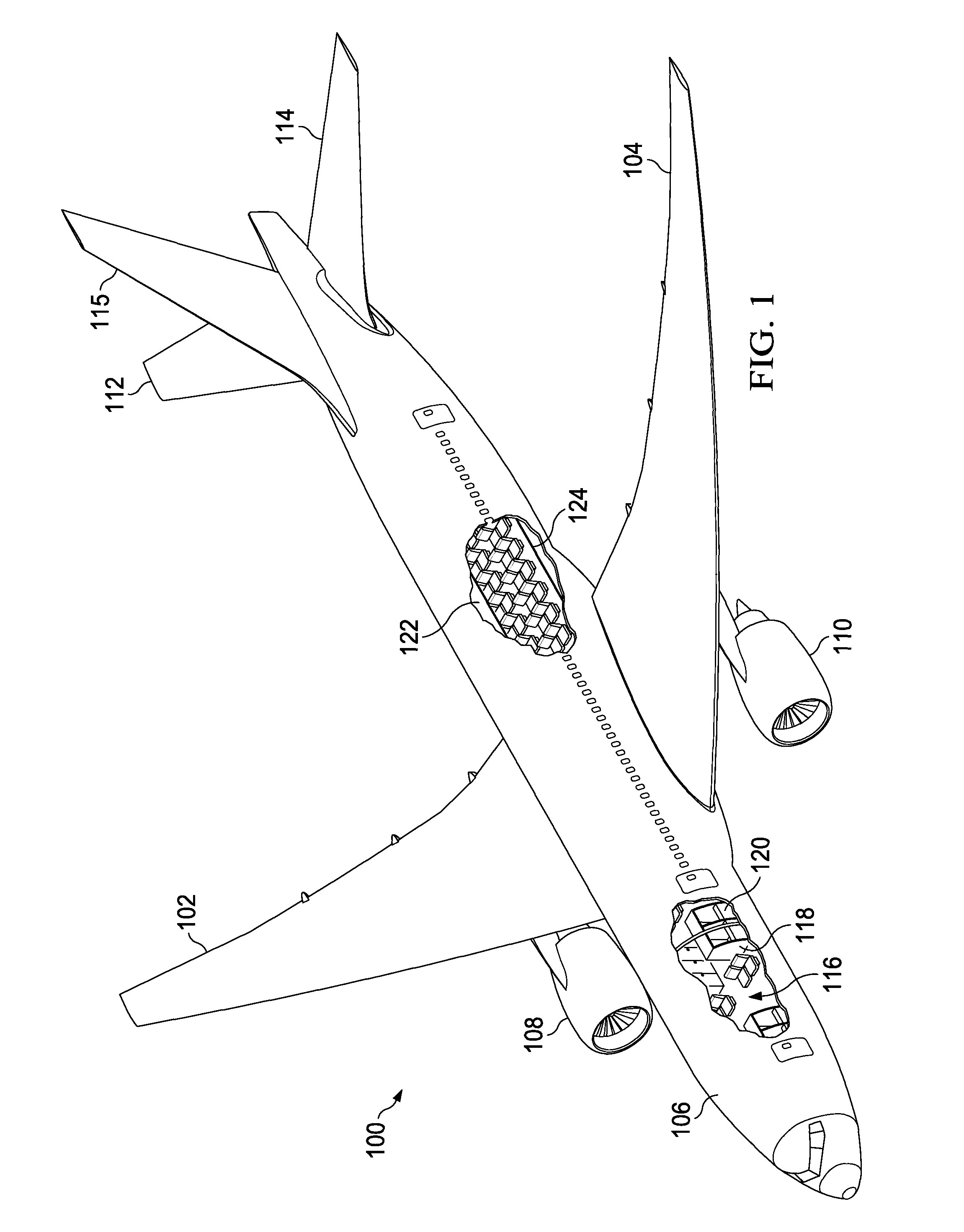
[0030]With reference now to the figures and, in particular, with reference to FIG. 1, an illustration of an aircraft is depicted in which an illustrative embodiment may be implemented. Aircraft 100 is an example of an aircraft in which noise reduction systems may be implemented in accordance with an illustrative embodiment.

[0031]In the illustrative example, aircraft 100 has wing 102 and wing 104 attached to fuselage 106. Aircraft 100 also includes engine 108 connected to wing 102 and engine 110 connected to wing 104. Aircraft 100 also has horizontal stabilizer 112, non-vertical stabilizer 114, and vertical stabilizer 115.

[0032]In these illustrative examples, noise reduction systems may be implemented in or with various composite components in aircraft 100. For example, a noise reduction system may be implemented in a composite panel for use within aircraft 100.

[0033]As depicted, an exposed view of interior 116 of aircraft 100 is shown. Within interior 116, one or more composite pane...


PUM

PropertyMeasurementUnit
frequenciesaaaaaaaaaa
frequencyaaaaaaaaaa

Abstract

A method and apparatus comprising a composite panel and a number of structures to reduce noise radiation from the composite panel. The composite panel has a first face sheet, a second face sheet, and a core located between the first face sheet and the second face sheet. The number of structures is associated with the first face sheet. The number of structures has a mass with a configuration to reduce a speed of waves propagating in the composite panel such that noise radiating from the composite panel is reduced.

Description

BACKGROUND INFORMATION[0001]1. Field:[0002]The present disclosure relates generally to aircraft structures and, in particular, to aircraft using composite structures. Still more particularly, the present disclosure relates to a method and apparatus for reducing noise in composite structures in an aircraft.[0003]2. Background:[0004]Aircraft are being designed and manufactured with greater and greater percentages of composite materials. For example, some aircraft may have more than 50 percent of their primary structures made from composite materials. Further, composite materials also may be used in the interior of the aircraft and for other structures.[0005]Composite materials are used in aircraft to decrease the weight of the aircraft. With the decreased weight, improved payload capacities and fuel efficiencies may occur. Further, composite materials also may provide a longer service life for various components in an aircraft.[0006]Composite materials have a lighter weight and greate...

Claims


Application Information

Patent Timeline
Patent Type & Authority Patents(United States)
IPC IPC(8): E04B1/82E04B2/02B32B3/12B64C1/40G10K11/00E04B1/84
CPCE04B1/82B64C1/40B64C1/066Y02T50/46Y10T428/24149Y02T50/40E04B1/86G10K11/172B32B3/12
Inventor MATHUR, GOPAL PRASADCHIN, CLIFF L.
Owner THE BOEING CO
Why Eureka
Try Eureka