Vehicle battery pack housing structure

a battery pack and housing technology, applied in the direction of battery/cell propulsion, cell component details, cell components, etc., can solve the problems of limiting the depth reducing the volume of the battery housing space, and limiting the size of the battery pack

Active Publication Date: 2014-07-15
NISSAN MOTOR CO LTD
View PDF10 Cites 21 Cited by
  • Summary
  • Abstract
  • Description
  • Claims
  • Application Information

AI Technical Summary

Benefits of technology

[0009]A certain degree of deep drawing can be achieved by increasing the radius of rounding at the intersection between the side walls of the battery housing space, and by providing a draft angle tilt to the side walls of the battery housing space. However, in order to enable deep drawing of a battery housing space for housing a large-sized battery pack, the radius of rounding at the intersection between the side walls and the tilt angle of the side walls is increased to a large degree. Thus, the volume of the battery housing space is significantly reduced, which limits the size of the battery pack and sacrifices battery capacity.
[0010]Therefore, an object of the present invention is to provide a battery pack housing structure for a vehicle, such as an electric or hybrid vehicle, that can avoid the above problems.

Problems solved by technology

The battery pack, which can also be referred to as a battery module, is generally heavy and large in size.
However, Japanese Laid-Open Patent Application No. 06-199183 fails to describe a specific procedure for providing the battery housing space as a downward-opening upward depression in the vertical direction of the vehicle body in a floor panel of the vehicle body.
Thus, Japanese Laid-Open Patent Application No. 06-199183 fails to problems such as those described below that can arise when a material is drawn to form the floor panel of a vehicle body and the downward-opening battery housing space is formed in the floor panel.
For example, the elongation limit of the panel material limits the depth of the battery housing space.
Thus, the volume of the battery housing space is significantly reduced, which limits the size of the battery pack and sacrifices battery capacity.

Method used


Image

  • Vehicle battery pack housing structure
  • Vehicle battery pack housing structure
  • Vehicle battery pack housing structure

Examples


Embodiment Construction

[0023]Selected embodiments will now be explained with reference to the drawings. It will be apparent to those skilled in the art from this disclosure that the following descriptions of the embodiments are provided for illustration only and not for the purpose of limiting the invention as defined by the appended claims and their equivalents.

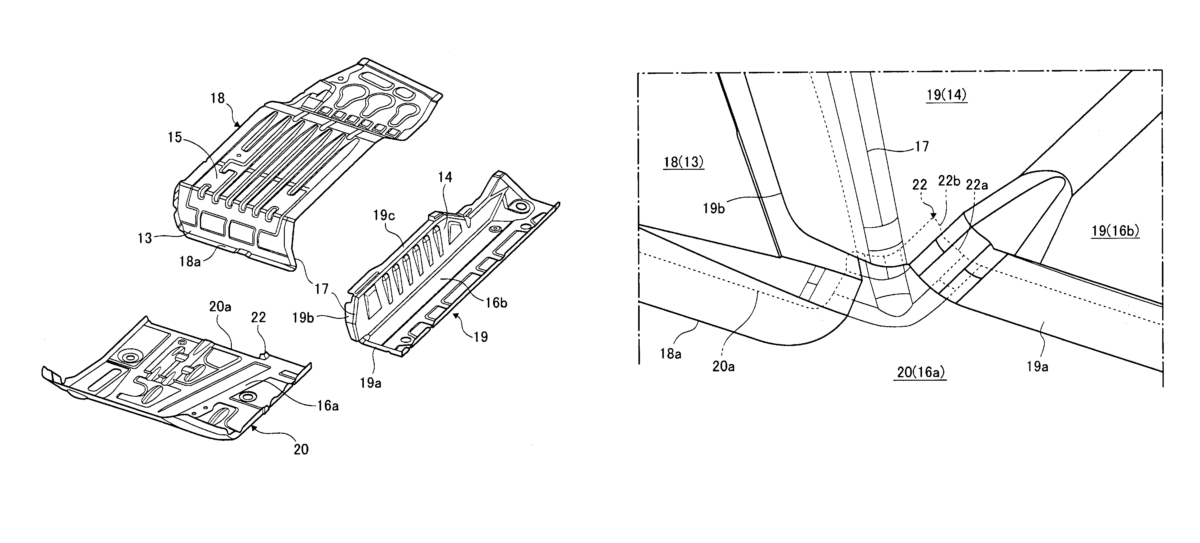
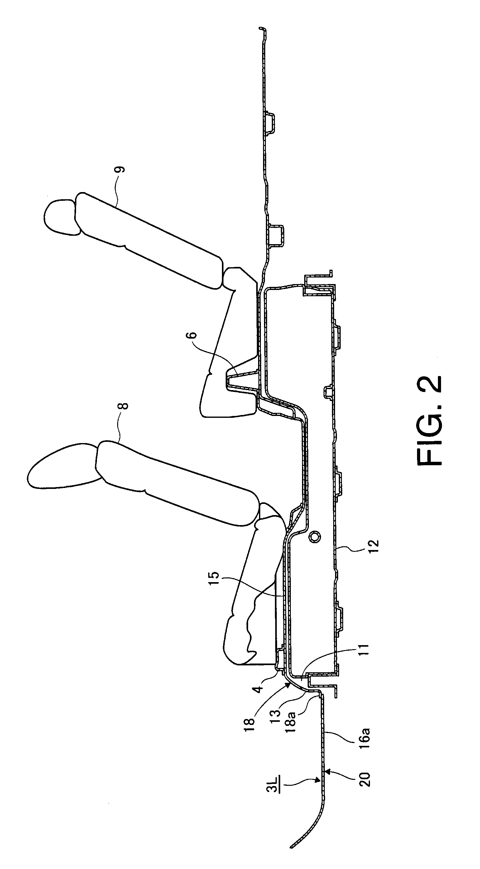
[0024]Referring initially to FIG. 1, a vehicle battery pack housing structure is illustrated in accordance with a first embodiment. FIG. 1 is a perspective view from above the left side of the vehicle, and shows the vehicle body floor portion the vehicle that is provided with the battery pack housing structure according to an embodiment. The vehicle can be an electric vehicle, a hybrid vehicle or any type of vehicle having components, such as an electric motor, that are powered by a battery. Furthermore, the vehicle can be a car, truck, van, SUV or any other suitable vehicle.

[0025]The vehicle body floor portion includes a vehicle body floor portio...


PUM

PropertyMeasurementUnit
angleaaaaaaaaaa
tensileaaaaaaaaaa
poweraaaaaaaaaa

Abstract

A vehicle battery pack housing structure includes a vehicle body panel and first, second and third panel components that define an outward-opening battery housing space. The first panel component is rigidly attached to the vehicle body panel and includes a first side wall and a base wall. The second panel component is rigidly attached to the first panel component and includes a second side wall and a first periphery wall portion. The third panel component is rigidly attached to the second panel component. The third panel component includes a second periphery wall portion that cooperates with the first periphery wall portion to form a periphery wall portion when the third panel component is rigidly attached to the second panel component.

Description

CROSS-REFERENCE TO RELATED APPLICATIONS[0001]This application is a U.S. National stage of International Application No. PCT / IB2011 / 001104, filed May 23, 2011. This application claims priority to Japanese Patent Application No. 2010-130769, filed on Jun. 8, 2010. The entire disclosure of Japanese Patent Application No. 2010-130769 is hereby incorporated herein by reference.BACKGROUND[0002]1. Field of the Invention[0003]The present invention generally relates to a vehicle battery pack housing structure. More particularly, the present invention relates to a vehicle battery pack housing for an electric vehicle, hybrid vehicle, or other type of vehicle having components, such an electric motor, powered by a battery.[0004]2. Background Information[0005]An electric or hybrid vehicle uses an electric motor as a source of power to propel the vehicle. Therefore, such a vehicle typically includes a large-capacity battery pack as a source of electrical power for the electric motor. A large capa...

Claims


Application Information

Patent Timeline
Patent Type & Authority Patents(United States)
IPC IPC(8): B60R16/04B60L50/64
CPCH01M2/10B60K1/04Y10S903/902B62D25/20H01M2/1077H01M2/1083B21D53/88B60K2001/0422B60K2001/0438Y02E60/12B60K2001/0433Y02E60/10H01M50/204H01M50/249B60L50/64Y02T10/70Y10T29/49826
Inventor AKAZAWA, DAISUKETERASHIMA, YASUTSUNE
Owner NISSAN MOTOR CO LTD
Why Eureka
Try Eureka