
Compact slot antenna

A slotted antenna, compact technology, used in antennas, slot antennas, antenna supports/mounting devices, etc., can solve problems such as the increase in the number of circuit board antennas

Inactive Publication Date: 2014-05-07
THOMSON LICENSING SA
View PDF7 Cites 6 Cited by
  • Summary
  • Abstract
  • Description
  • Claims
  • Application Information

AI Technical Summary

Problems solved by technology

The application of MIMO circuits usually results in an increase in the number of antennas implemented on a single board

Method used


Image

  • Compact slot antenna
  • Compact slot antenna
  • Compact slot antenna

Examples


Embodiment Construction

[0026] First, refer to Figure 4 to Figure 6 Two embodiments of a compact slotted antenna of electrical length λg / 2 realized on a multilayer substrate are described.

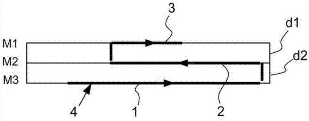
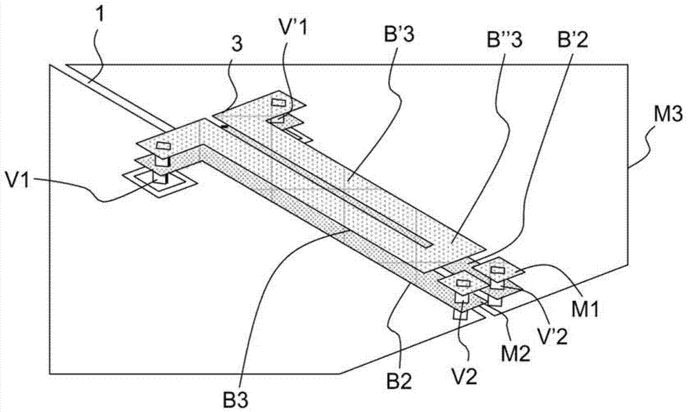
[0027] As shown more specifically in Figures 4(A) and 4(B), a multilayer substrate is a substrate that includes two dielectric layers d1 and d2 and three conductive layers, respectively, of the dielectric layer d1 An upper conductive layer M1 on the upper surface, an intermediate conductive layer M2 between the dielectric layers d1 and d2, and a lower conductive layer M3 on the lower surface of the dielectric layer d2.

[0028] In the two embodiments of Fig. 4(A) and 4(B), the slotted antenna is firstly formed by the slot line 10 etched in the middle conductive layer M2, and is fed by electromagnetic coupling with the feed line at the feeding point 13. In, the feeder is implemented by microstrip technology, either on the upper surface of the dielectric layer d1 or on the lower surface of the dielectric layer d2...


PUM


Abstract

The present invention relates to a compact slot antenna formed, in a multilayer substrate comprising, in order, at least one first conductive layer, a first dielectric layer, a second conductive layer, a second dielectric layer and a third conductive layer, of a first slot-line (30) realised in the second conductive layer, said first slot-line being connected to the supply (A) of the antenna, of a second and a third slot-lines realised respectively in the first and in the third conductive layers, the second and third slot-lines (31, 32) each being delimited by two conductive strips of which a first extremity, supply side, is interconnected by a via passing through a window realised in the second conductive layer and a second extremity connected to the second conductive layer, both conductive strips on the side of the second extremity being, either in open circuit, or in short circuit, the electrical length of the first, second and third slot-lines being a function of the wavelength at the operating frequency of the antenna.

Description

technical field [0001] The present invention generally relates to a compact slotted antenna. More specifically, it relates to compact slotted antennas implemented in multilayer substrates. Background technique [0002] In the field of wireless communication, in order to increase the capacity of transmission circuits and improve the operability of the overall system, MIMO (Multiple Input Multiple Output) circuits are increasingly used. The application of MIMO circuits generally results in an increase in the number of antennas implemented on a single circuit board. In addition, in order to facilitate circuit integration, current antennas are directly generated on printed circuit boards or PCBs. However, applying the laws of physics, the length of the antenna is a function of wavelength. Therefore, for wireless applications, for example, in the 2.4 GHz frequency band, the length of the slotted antenna (as a function of λg) is tens of millimeters. This length is not negligib...

Claims


Application Information

Patent Timeline
IPC IPC(8): H01Q1/38H01Q13/10
CPCH01Q13/16H01Q21/28H01Q1/24H01Q13/10H01Q13/106
Inventor D.洛钦顿K.纳杜德P.米纳德F.巴隆
Owner THOMSON LICENSING SA
Learn More