Hydraulic boat hoist

a hoist and hydraulic technology, applied in the field of boat hoists, can solve the problems of cable fatigue, many weaknesses of pole winders, and inability to allow private ownership of waterfront properties

Active Publication Date: 2014-07-15
MIDWEST INDS
View PDF13 Cites 3 Cited by
  • Summary
  • Abstract
  • Description
  • Claims
  • Application Information

AI Technical Summary

Benefits of technology

[0019]The present invention relates to a hydraulic lift system is a roof or pile-mounted lift system. The unique design uses a pair of hydraulic cylinders to pull a system of lift cables. The cable system is strung through a tube with large diameter sheaves. This design totally eliminates the cable fatigue caused by winding cables.
[0021]One aspect of the hydraulic system of the present invention eliminates the need to run A / C power under water to other motors. The pressure from the hydraulic power unit can be delivered to multiple cylinders through hoses that can be run under water or overhead if a roof structure exists. This allows DC power to be used and eliminates the burden on the A / C supply circuit. Using a volume-leveling hydraulic system eliminates the user intervention required by multi-motor systems. Any out of synchronization that occurs is automatically corrected at the end of the lifting process with a unique pair of switches wired in parallel. This makes everyday operation fast and user friendly.
[0023]The hydraulic system is designed to allow fluid ‘bypass’ when a lift cylinder reaches the end of its stroke. This allows the lift cylinders to automatically ‘level up’. If one cylinder fully retracts before the other, the hydraulic power unit can continue to retract the other cylinder. This auto-level function eliminates the need for a user to manually level the lift using switches to control individual motors.

Problems solved by technology

Many reservoirs do not allow private ownership of waterfront property.
Pole-winders have many weaknesses that present opportunities.
Cable fatigue, motor synchronization, slow speed, poor corrosion resistance, and power supply issues are a short list of issues with current products.
Cable fatigue is in a guaranteed failure mode if cables are not replaced every 2-3 years, depending on frequency of use.
The galvanized poles used in these designs cause rapid fatigue of the cables because of the small winding diameter.
Compounding the issue is the large lift height requirement for most installations.
This not only fatigues the cable, but also damages the individual wires with the wire rope.
Cable failure modes are severe and cause the boat to fall in one direction endangering people and equipment.
Motor synchronization is also an issue in multi-pole / motor setups.
Compounding this issue is the slow speed of the pole winding systems.
The galvanized construction of the pole winding systems is adequate for most environments, but they eventually rust as the wound areas of the poles lose their zinc coating.
This length is too long for a DC (12-24V) power supply to run without extremely heavy wire.
This often creates a large voltage drop along the circuit.
The voltage drop can cause the system to malfunction and reduce the life of the motor(s) in the system.
A / C power can be dangerous system in wet environments.
Many lives have been lost due to damaged A / C circuits causing stray A / C currents in lakes and waterfronts with inadequate circuit protection.
This hydraulic system is innovative, but expensive.
This jeopardizes the durability of the system.
As air is evacuated from the floats gravity will cause the structured to sink to the lakebed unless a structure is in place to limit the travel.
This lift style does not work well in shallow areas because of the size of the floating structure.
Users often complain about this requirement and the difficulty controlling it.
This can cause corrosion and pitting of the rod surface which will cause leaking of the hydraulic seals.

Method used


Image

  • Hydraulic boat hoist
  • Hydraulic boat hoist
  • Hydraulic boat hoist

Examples


Embodiment Construction

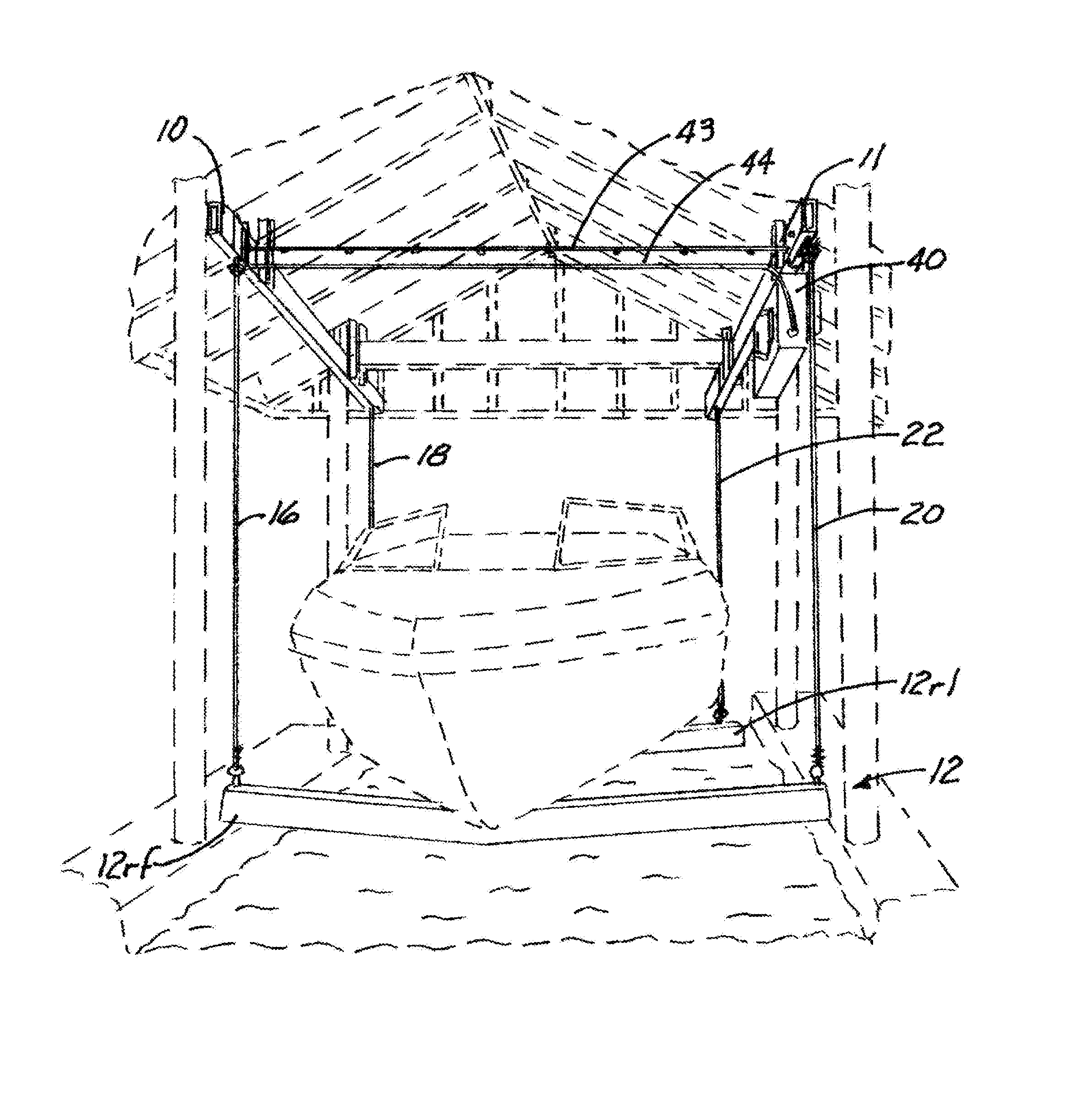
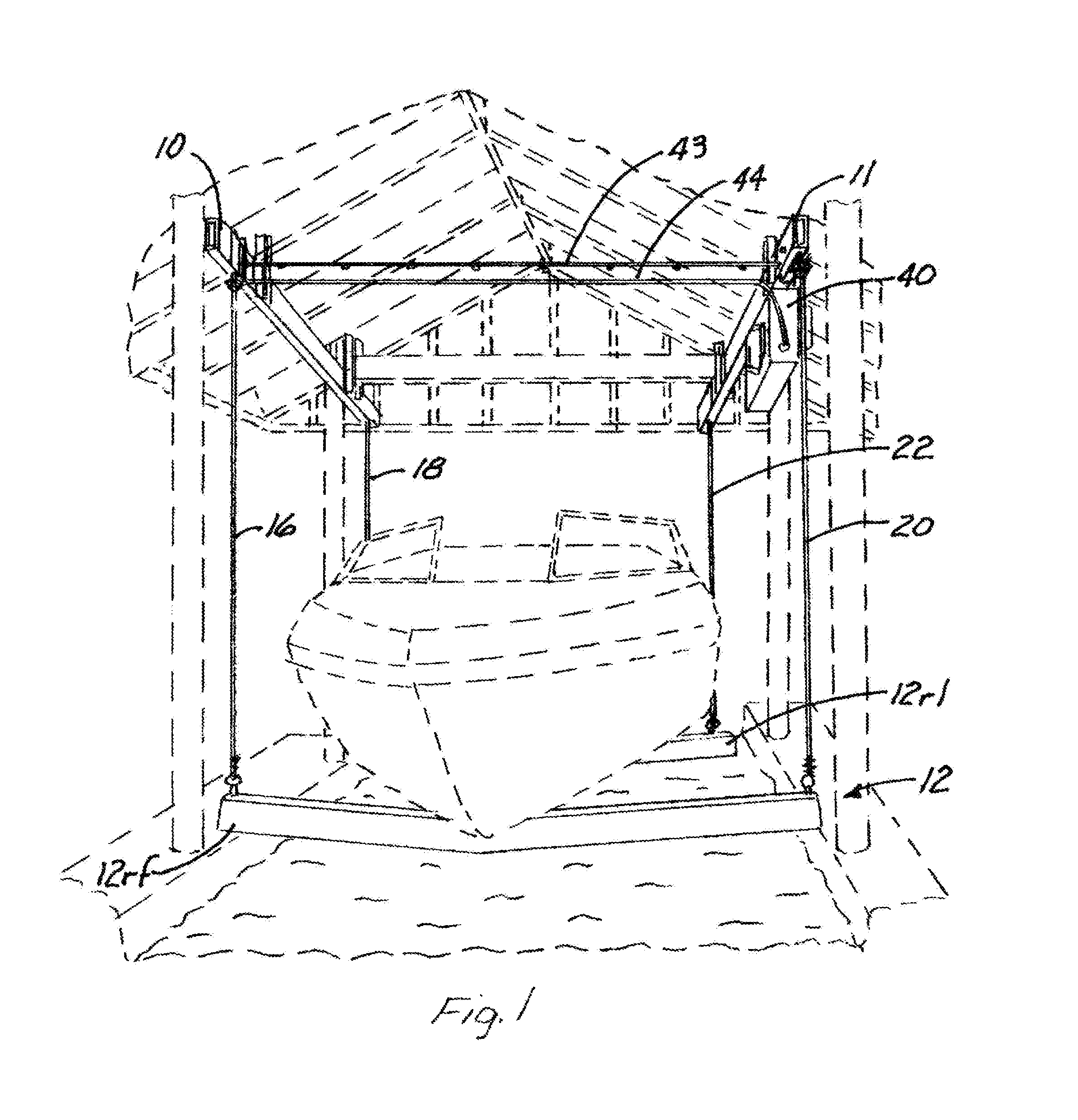
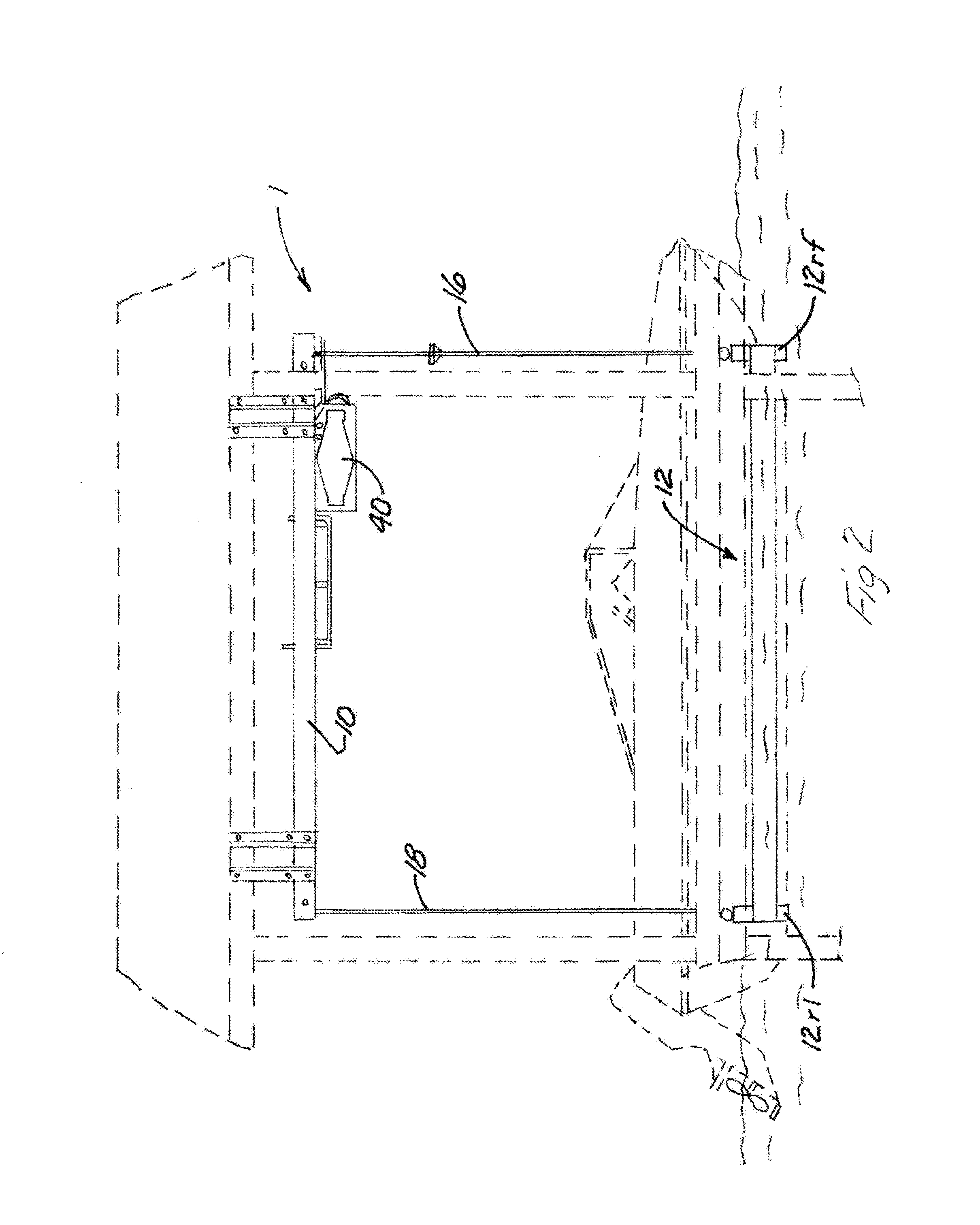
[0045]Referring now to the drawings, wherein like reference numerals designate identical or similar parts throughout the several views, FIGS. 1-11 and FIGS. 15-18 show a hydraulic boat hoist 10 constructed in accordance with a preferred embodiment of the invention for connection to a boat house shown in dashed lines. FIGS. 12 and 13 show the preferred embodiment attached to piers instead of to a boat house.

[0046]The boat lift (1) shown in FIGS. 1-4 is shown specifically installed in a boat house shown in dashed lines in FIGS. 1-3. The hydraulic boat lift (1) has a pair of lift tubes (10) and (11) which will be referred to herein first and second elongated members (10) and (11). These elongated members (10) and (11) are attached to structures within the boat house but can also be attached directly to piers for example in the manner shown in FIGS. 12 and 13.

[0047]A boat lifting platform (12), shown in FIG. 1 for example, has a front portion with a right front portion (12rf) and a fron...


PUM


Abstract

A hydraulic boat lift uses two hydraulic cylinders to pull / release cables attached to a boat cradle. The hydraulic cylinders are operated by attachment to a tandem pump to cause them to operate in a synchronized fashion. Furthermore a switch assembly has a switch associated with each respective hydraulic cylinder, the pair of switches being wired in parallel so that if one side of the boat cradle reaches its fully raised position before the other side, the one side will stop and the other side will continue to move up until it is also disposed in a fully raised position before stopping by turning off the electricity to the tandem pump.

Description

TECHNICAL FIELD[0001]This invention relates generally to boat hoists and more particularly to a boat hoist for use on piling posts secured to the bottom of the body of water and / or boat houses built on such pilings.BACKGROUND[0002]Hydraulically actuated boat hoists are shown in U.S. Pat. No. 6,823,809 to Hey, U.S. Pat. No. 6,976,442 to Hey U.S. Pat. No. 7,246,970 to Hey, U.S. Pat. No. 7,413,378 to Way and U.S. Pat. No. 8,267,621 to Way, all of which are incorporated herein by reference in their entirety.[0003]Southern U.S. States and coastal regions commonly use one of these three methods to store / moor boats: (1) Moor the boat to a fixed or floating pier using ropes. In this case, the boat remains in the water, (2) lift the boat using a platform or sling type lift mounted to a set of pilings or roof structure mounted on pilings, or (3) lift the boat using a floating lift system. The most common method used depends on the region and regulations governing the body of water. Many reser...

Claims


Application Information

Patent Timeline
Patent Type & Authority Patents(United States)
IPC IPC(8): B63C1/08
CPCF15B15/04B63C3/06F16H19/08
Inventor DEVITT, JON, W.
Owner MIDWEST INDS
Why Eureka
Try Eureka