Energy saving green wastewater pump station design

a technology of waste water pump station and green technology, applied in the direction of pump control, positive displacement liquid engine, pump, etc., can solve the problems of increased maintenance requirements of pumps operating under this design, inefficient design and maintenance, and loss of kinetic energy, so as to reduce the amount of energy, minimize the requirement of pump horse power, and reduce the effect of friction resistan

Active Publication Date: 2014-07-15
MEHR NASSER FRED
View PDF5 Cites 3 Cited by
  • Summary
  • Abstract
  • Description
  • Claims
  • Application Information

AI Technical Summary

Benefits of technology

[0006]One object of this invention is to reduce amount of energy to operate a waste water pump station through a green design that utilizes three motors of equal horsepower with the primary pump running continuously, the second pump running when demand exceeds the capacity of the first pump and the third pump serving as a back up, emergency pump. The determination of the most efficient horsepower to be used in the station is based on 24 hour flow rates, well capacity, required head and the discharge force main diameter and length. A system curve calculating the pipe layout having the least friction resistance is also utilized to minimize pump horse power requirements thereby further reducing energy consumption. From this data, the pump performance curve is established providing the most efficient point of operation for the Energy Saving Green Waste Water Pump Station three pump system design which can be compared to that of the inefficient traditional two pump waste water pump station. Similar calculations and the resulting energy savings apply to traditional pump stations with more than two pumps.
[0007]The second object of this invention is to reduce maintenance costs and extend the useful lives of pumps in waste water pump stations. This is accomplished by reducing start-stop cycles, reducing heat build up around pumps when they turn off (short cycling resulting in insufficient time for the generated heat of the previous start to be dissipated), reduction of excessive resistive torque from debris to entering impellers in the off position during settling. In addition, this method cycles the three pumps by rotating the primary continuous running pump with the secondary support pump and the backup third pump on a scheduled basis. In this way the pumps are kept at the optimal level of failure resistance unlike pumps in the conventional design.

Problems solved by technology

The design is very inefficient and maintenance intensive.
Also, each time a pump turns off, kinetic energy is lost.
In addition, maintenance requirements for pumps operating under this design are increased since stagnated waste water accumulating around an idle pump impeller enables debris to enter the immobilized impeller due to loss of the excessive resistant torque of a running pump.
Traveling during rush hour, with traffic constantly slowing down (comparative to modern pumps that use variable frequency drives) or stopping and going (comparative to older, less expensive, traditional pumps) results in miles per gallon loss compared to traffic running at the most efficient engine speed of an automobile (driving steadily at 45 mph on average).
Also the wear and tear of stopping and going causes more maintenance to an automobile's parts than does that occurring from driving at a constant energy efficient speed.

Method used


Image

  • Energy saving green wastewater pump station design
  • Energy saving green wastewater pump station design
  • Energy saving green wastewater pump station design

Examples


case i

Traditional Waste Water Pump Station with Two Pumps 160 GPM, 60 ft Head Each Pump

[0054]The product of EBARA INTERNATIONAL CO. has been used in this study. For a pump station with two pumps 104 and 106, 160 GPM, a total head of 60 ft of water, the submersible pump 104 and 106 from the group of DSU of EBARA was selected as:

[0055]Model No. 80 DS63.7, 5HP, Synchronous Speed of 3600 RPM, 3″ Discharge, Solid Diameter ⅜″. The pump 104 and 106 performance curves are given in FIG. 6a and FIG. 6b.

[0056]In this graph, the point of operation is between two curves of impeller 126 mm and 114 mm. The impeller of 126 mm should be trimmed down to 308.5 mm.

Wet Well 102 Dimension & Storage Capacity—

[0057]Wet wells 102 usually are in the shape of a cylinder and are constructed from reinforced concrete. In addition to housing the pumps 104 and 106, the wet well's 102 function as a fluid storage container that regulates the discharge flow 134. The storage capacity of several wet wells 102 for one ft. of...

case-ii

Pump Station with Three Pumps 220

80 GPM, 60 ft Head Each Pump

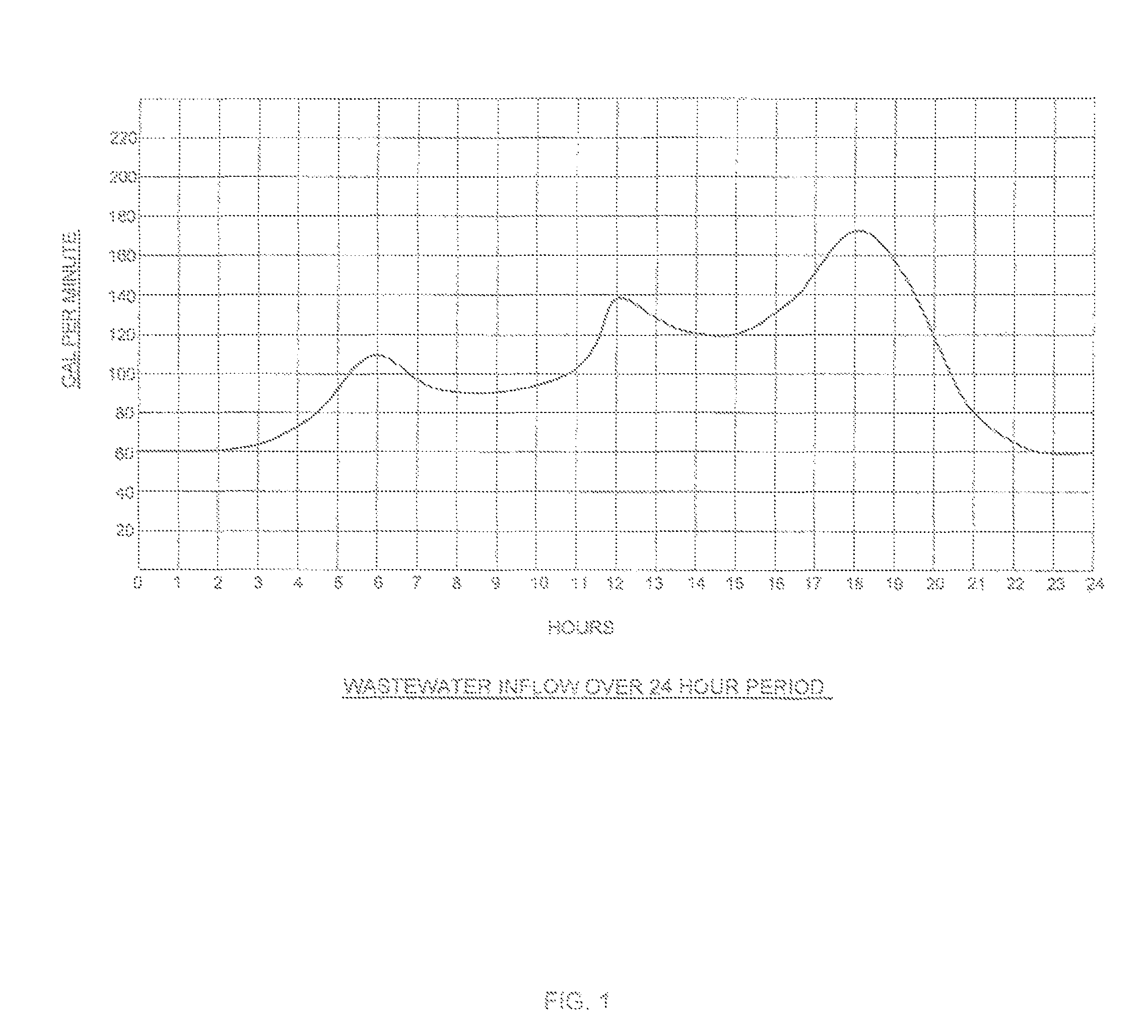
[0064]In this design 220, the same in-flow profile for 24 hours of FIG. 1 was used. The pump station 220 has the following specifications:

1—The wet well 200 is a concrete cylinder of 8 feet diameter with a depth of 18 feet.

2—The lateral force main 126 is a 4 inch pipe and identical to the design of the two pump waste water pump station 112; therefor, the system curve is the same and the total head for the pump station will be 60 feet.

3—The design pump 224, 226 and 228 GPM, in contrary to the two pump system 112, is associated with the minimum in-flow rate which is almost 50% of the maximum in-flow. The flow rate of 80 GPM has been selected for the pumps 224, 226 and 228.

4—The pump station has three identical pumps 224, 226 and 228, each with 80 GPM and a total head of 60 feet of water.

5—In this design, the effort was to modify the traditional two pump station 112 to a more efficient one 220 for the purpose of analysis and ...

case ii

5—Numerical Values for Case I and Case II Pump Stations—

[0097]Discharge static head and suction static head for pump stations with the traditional two pump design (case 1) 112 and the Three Pump Energy Saving Green Pump Station Design (case II) 220 have been tabulated as (TABLE 3):

[0098]

TABLE 3PUMP#1PUMP#2PUMP#3CASE ITWO PUMP LIFT-STATIONOPERATING CONDITIONSONLY PUMP#1 RUNSBOTH PUMPS RUNDISCHARGE STATIC HEAD17.5 FEET17.5 FEETSUCTION STATIC HEAD−5.5 FEET−12.5 FEET FOR BOTHCASE IITHREE PUMP LIFT-STATIONOPERATING CONDITIONSONLY PUMP#1 RUNSBOTH PUMPS 1 AND 2 RUNALL THREE PUMPS RUNDISCHARGE STATIC HEAD  16 FEET  16 FEET16 FEETSUCTION STATIC HEAD−7.5 FEET−10.5 FEET FOR−13.5 FEET FORBOTH PUMPSALL THREE PUMPS

6—Actual Friction Loss—

[0099]Design friction loss is based on design GPM of the force main 300 / 302 at the maximum GPM. However, most of the time the actual flow rate is less than the maximum GPM. The actual friction loss can be calculated by the following equation:

DH=f×L / D×V2 / 2g ACTUAL ...


PUM


Abstract

An energy saving three pump waste water pump station design that eliminates the high energy usage of traditional waste water pump stations, reduces maintenance costs to the pumps and increases the useful lives of the pumps by having a primary pump running continuously, a second pump mining during high demand periods and a third pump functioning primarily as a back up pump. Unlike conventional pump-station designs, the Energy Saving Green Pump Station Design utilizes a single float switch panel. Whereas independent float switches trigger start-stops in conventional pump station designs, the Green design incorporates a remote controllable panel for rotating the primary, secondary and third pumps on a schedule. This design also provides a process for determining in-flow rates for a pump station and efficiency operating points of pumps so that the most efficient pumps with the lowest horsepower can be selected.

Description

BACKGROUND OF INVENTION[0001]This invention relates to the improved design of waste water pump station pumping systems for the purpose of more efficient utilization and conservation of energy resources. The invention applies to two pump, waste water pump stations as well as pump stations having three or more pumps.[0002]The conventional waste water pump station design employs two or more pumps. In two pump waste water pump station systems, one pump must be large enough to handle the in flow at any given time. The second pump is the stand bye, backup pump. It will turn on if the first pump fails. It also will turn on if, for some reason, the in flow rate exceeds the maximum capacity of the first pump under emergency conditions. The design is very inefficient and maintenance intensive. First off, the primary pump turns on and off each time the volume of fluid in the well reaches maximum and minimum levels respectively. The energy required to turn on a pump is significantly higher than...

Claims


Application Information

Patent Timeline
Patent Type & Authority Patents(United States)
IPC IPC(8): F04B49/04F04B41/06
CPCF04B23/04
Inventor MEHR, NASSER, FRED
Owner MEHR NASSER FRED
Why Eureka
Try Eureka