Method for producing reversible thermosensitive recording medium, production apparatus for the same, and reversible thermosensitive recording medium

a technology of thermosensitive recording medium and production apparatus, which is applied in the direction of process and machine control, mechanical control devices, instruments, etc., can solve the problems of reducing the efficiency of positioning adjustment, affecting the quality of the resulting product, and the bottleneck of reducing the total thickness of the reversible thermosensitive recording medium, etc., to achieve high precision

Inactive Publication Date: 2014-07-15
RICOH KK
View PDF13 Cites 0 Cited by
  • Summary
  • Abstract
  • Description
  • Claims
  • Application Information

AI Technical Summary

Benefits of technology

[0020]An object of the present invention is to provide a method for producing a reversible thermosensitive recording medium and a reversible thermosensitive recording medium production apparatus each of which enables aligning, with high precision, a convex-shaped electronic information recording element with a concave portion in which the convex-shaped electronic information recording element is housed, so that the recording element is laminated on a base sheet, preventing air bubbles from being included in the reversible thermosensitive recording medium to prevent recording failure and print failure caused by concave-convexes of a surface of the recording medium, continuously producing a reversible thermosensitive recording medium with high efficiency, and further producing reversible thermosensitive recording media having a variety of different sizes; and a reversible thermosensitive recording medium obtained by the method and apparatus.
[0074]The present invention can solve the above-mentioned conventional problems and achieve the above-mentioned object. That is, the present invention can provide a method for producing a reversible thermosensitive recording medium and a reversible thermosensitive recording medium production apparatus each of which enables aligning, with high precision, a convex-shaped electronic information recording element with a concave portion in which the convex-shaped electronic information recording element is housed, so that the recording element is laminated on a base sheet, preventing air bubbles from being included in the reversible thermosensitive recording medium to prevent recording failure and print failure caused by concave-convexes of a surface of the recording medium, continuously producing a reversible thermosensitive recording medium with high efficiency, and further producing reversible thermosensitive recording media having a variety of different sizes; and a reversible thermosensitive recording medium obtained by the method and apparatus.

Problems solved by technology

However, the thickness of an IC chip of an electronic information recording element cause a bottleneck to reduce the total thickness of a reversible thermosensitive recording medium.
However, in this proposal, the laminating the base material with the inlet is designed as an intermittent operation in which a stop of the lamination and conveyance are intermittently repeated, and these members are laminated in an area contact during stop of the operation, and thus, unfavorably, air bubbles are easily included between the base material and the inlet in the lamination process.
When this operational process is performed intermittently, it is difficult to uniformly apply the adhesive to the base material in the conveyance direction of the base material, the thickness of the resulting product is liable to vary, in addition to decreasing in the efficiency of positioning adjustment.
Therefore, the proposal has a drawback in that the position of the IC chip cannot be detected and lamination ensuring high-precision positioning cannot be achieved.
The above-mentioned problems cause concave-convex portions in a surface of a reversible thermosensitive recording medium, and this leads to recording failure and erasure failure in printing with a printer.

Method used


Image

  • Method for producing reversible thermosensitive recording medium, production apparatus for the same, and reversible thermosensitive recording medium
  • Method for producing reversible thermosensitive recording medium, production apparatus for the same, and reversible thermosensitive recording medium
  • Method for producing reversible thermosensitive recording medium, production apparatus for the same, and reversible thermosensitive recording medium

Examples


first embodiment

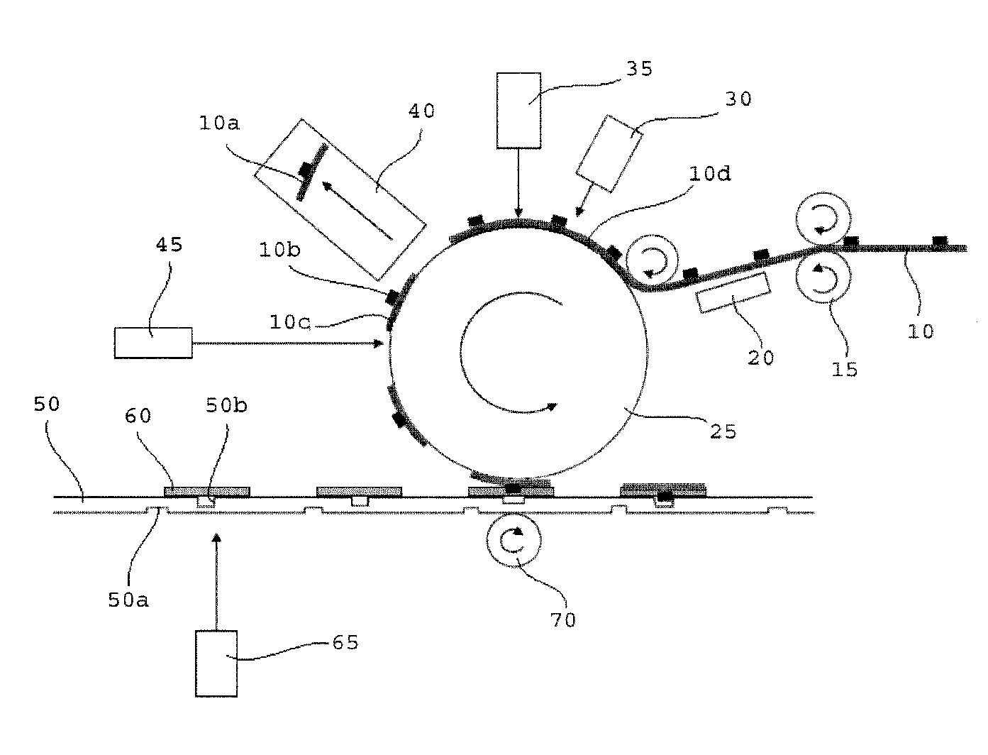
[0262]In FIG. 3, an inlet sheet 10 (produced by Hitachi Ltd., HIBIKI, HE-MU384-I002E) is straightly conveyed onto a rotating cylindrical-shaped vacuum suction roller 25 by infeed rollers 15 (nip roller), so as to mount an inlet. Here, the adsorption of the vacuum suction roller 25 is always turned on, and when the inlet sheet 10 is straightly conveyed thereon, the vacuum suction roller 25 starts adsorbing.

[0263]Just before the absorption, register mark 10d (or an IC portion) on the inlet is detected by an inlet position detecting sensor 30, and then the inlet sheet 10 is conveyed only at a certain distance by the driving of the infeed rollers 15 so as to locate in a position at a certain angle of the vacuum suction roller 25 based on the result of detection.

[0264]At this time, the inlet sheet 10 is conveyed by the infeed rollers 15 at the same speed as that of the vacuum suction roller 25 according to the travel of the inlet position by the rotation of the vacuum suction roller 25 s...

second embodiment

[0303]A production process according to a second embodiment will be described with reference to FIG. 5. An inlet sheet 10 is conveyed at a pitch on a one-sheet-paper basis by rotation driving of a cylindrical-shaped infeed roller 110, and cut into a plurality of inlets by a cutting device 120.

[0304]At this time, the communication function of an inlet 100 is tested by a testing device 115, and an inlet 100a evaluated as communication failed is removed by a rejection device 190.

[0305]Meanwhile, an inlet 100b involving no communication failure is stocked in a stocking device 130.

[0306]Subsequently, the inlet 100b is conveyed to a pick-up standby position 140a on one-sheet basis by an inlet conveyance roller 160, picked up by a pick-and-place device 140 and then transferred onto a conveyance roller 150 at an arbitral position 140b of the vacuum suction roller 150.

[0307]The subsequent steps are the same ones as in the first embodiment, and the description is omitted.

third embodiment

[0308]The production process according to a third embodiment will be described with reference to FIG. 6A. FIG. 6A is a view illustrating one example of a lamination aspect in a lamination step.

[0309]In this conveyance aspect, when a cut-out inlet from an inlet sheet 500 (fed through feed rollers 510 and advanced by a suction roller 520) is laminated with a base sheet 530, the base sheet 530 is allowed to enter a nip portion 570 along an inclined direction 530a so that the angle of the base sheet 530 proceeding to a position of lamination has an inclined angle 560 which is inclined perpendicularly downward a tangential direction in the nip portion 570.

[0310]By performing such lamination, it is possible to prevent inclusion of air bubbles between the inlet and the base sheet 530.

[0311]Production contents other than described above are the same as in the first embodiment, and the description is omitted.


PUM

PropertyMeasurementUnit
pressureaaaaaaaaaa
inclined angleaaaaaaaaaa
thicknessaaaaaaaaaa

Abstract

The present invention provides a method for producing a reversible thermosensitive recording medium, the method including: conveying an inlet sheet which includes inlets each having a convex-shaped electronic information recording element, retrieving positional information of the inlets, cutting the inlet sheet into individual inlets, retrieving positional information of the convex-shaped electronic information recording element in the individual inlets, conveying a base sheet, which includes concave portions, toward the vacuum suction roller, retrieving positional information of the concave portions, aligning the convex-shaped electronic information recording element with the concave portions so as to be inserted into the concave portion, and laminating the inlets and the base sheet.

Description

BACKGROUND OF THE INVENTION[0001]1. Field of the Invention[0002]The present invention relates to a method for producing a reversible thermosensitive recording medium having an inlet (electronic information recording section), a production apparatus for the same, and a reversible thermosensitive recording medium.[0003]2. Description of the Related Art[0004]IC cards have been increasingly used in various aspects from users' daily lives to business activities. Actually, they are used as various cards (e.g., cash cards, credit cards, prepaid cards and ETC cards (electronic toll collection system)); in transportation facilities (e.g., railways and buses); as affiliate cards for digital broadcasting, 3rd generation mobile phones, etc.; in library service counters; and as student ID cards, employee ID cards, basic resident register cards, etc. Meanwhile, the amount of IC cards disposed of has been being increasing in accordance with diversification of the current economic and social activi...

Claims


Application Information

Patent Timeline
Patent Type & Authority Patents(United States)
IPC IPC(8): B32B41/00
CPCG06K19/07749G06K19/07718G06K19/07722G06K19/07747G06K19/07775
Inventor OWASHI, TAKESHIKOGA, NOBORU
Owner RICOH KK
Why Eureka
Try Eureka