Dispersion compensation in chirped pulse amplification systems

a technology of chirped pulse and amplification system, which is applied in the direction of electromagnetic transmission, instruments, transmission, etc., can solve the problems of difficulty in calibration and high cost of option, and achieve the effects of improving system performance and lifetime, low cost, and rapid adjustmen

Active Publication Date: 2014-07-15
LAWRENCE LIVERMORE NAT SECURITY LLC
View PDF11 Cites 14 Cited by
  • Summary
  • Abstract
  • Description
  • Claims
  • Application Information

AI Technical Summary

Benefits of technology

[0009]Numerous benefits are achieved by way of the present invention over conventional techniques. For example, the present technique provides a method to compensate for spectral dispersion using passive techniques that do not require active control. Moreover, embodiments of the present invention utilize no moving parts, improving system performance and lifetime. Additionally, no power is utilized to operate the dispersion correction element in embodiments of the present invention. The dispersion compensator described herein is easily removed from the optical system and can be adjusted rapidly if changes are made in the optical system. Furthermore, embodiments of the present invention provide a low cost solution to the problem of compensating for dispersion in CPA systems, utilizing only a glass plate that has been finished using an MRF polishing step. Depending upon the embodiment, one or more of these benefits may be achieved. These and other benefits will be described in more detail throughout the present specification and more particularly below.

Problems solved by technology

The AOPDF is programmable and adaptive, however this option is costly and has to be actively controlled for the laser system to operate properly.
The SLM, for example, a liquid crystal SLM, is also programmable and adaptive, however this option suffers from discreet “pixels” of adjustable phase delay as well as difficulty during calibration.

Method used


Image

  • Dispersion compensation in chirped pulse amplification systems
  • Dispersion compensation in chirped pulse amplification systems
  • Dispersion compensation in chirped pulse amplification systems

Examples


Embodiment Construction

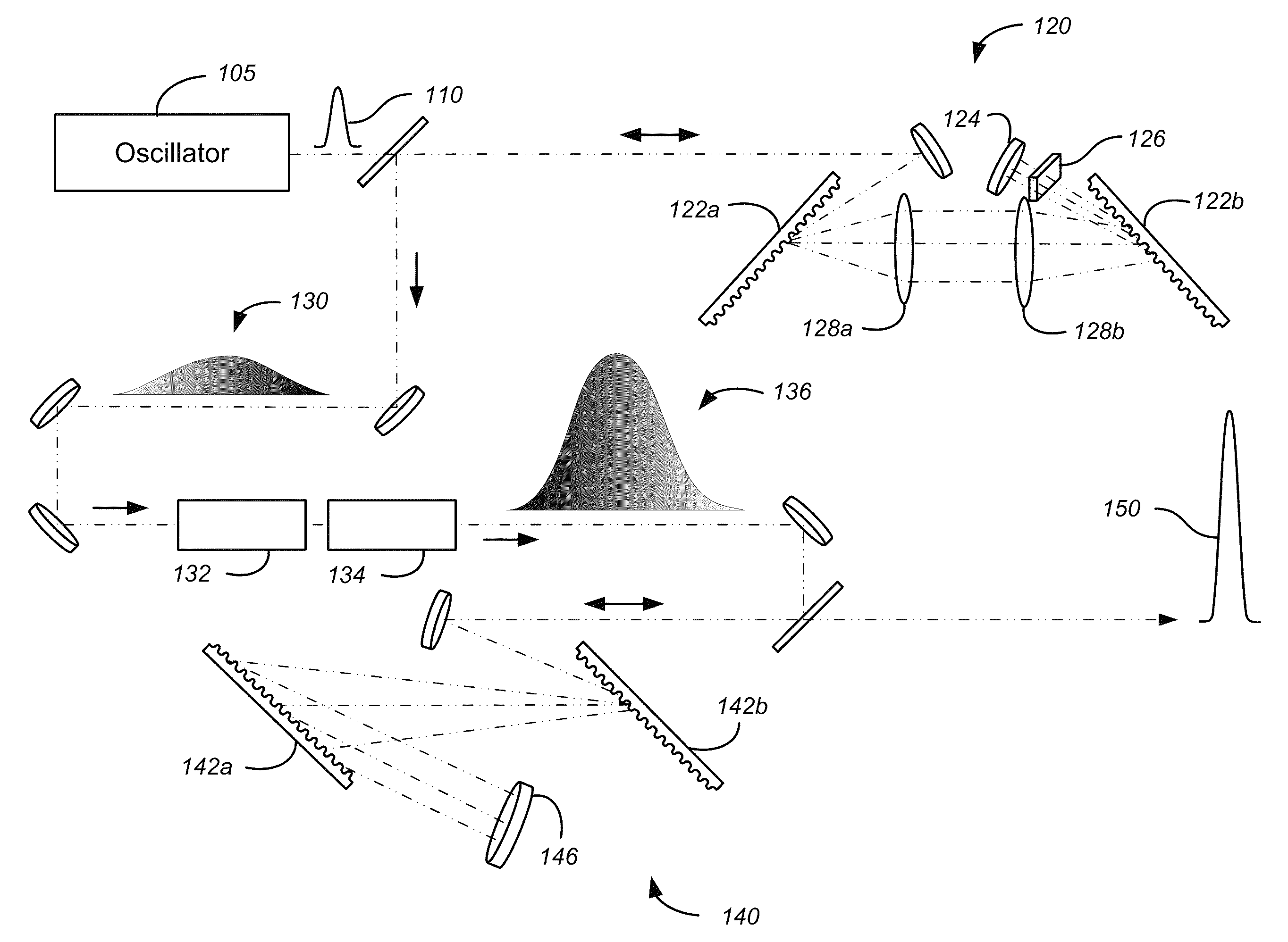
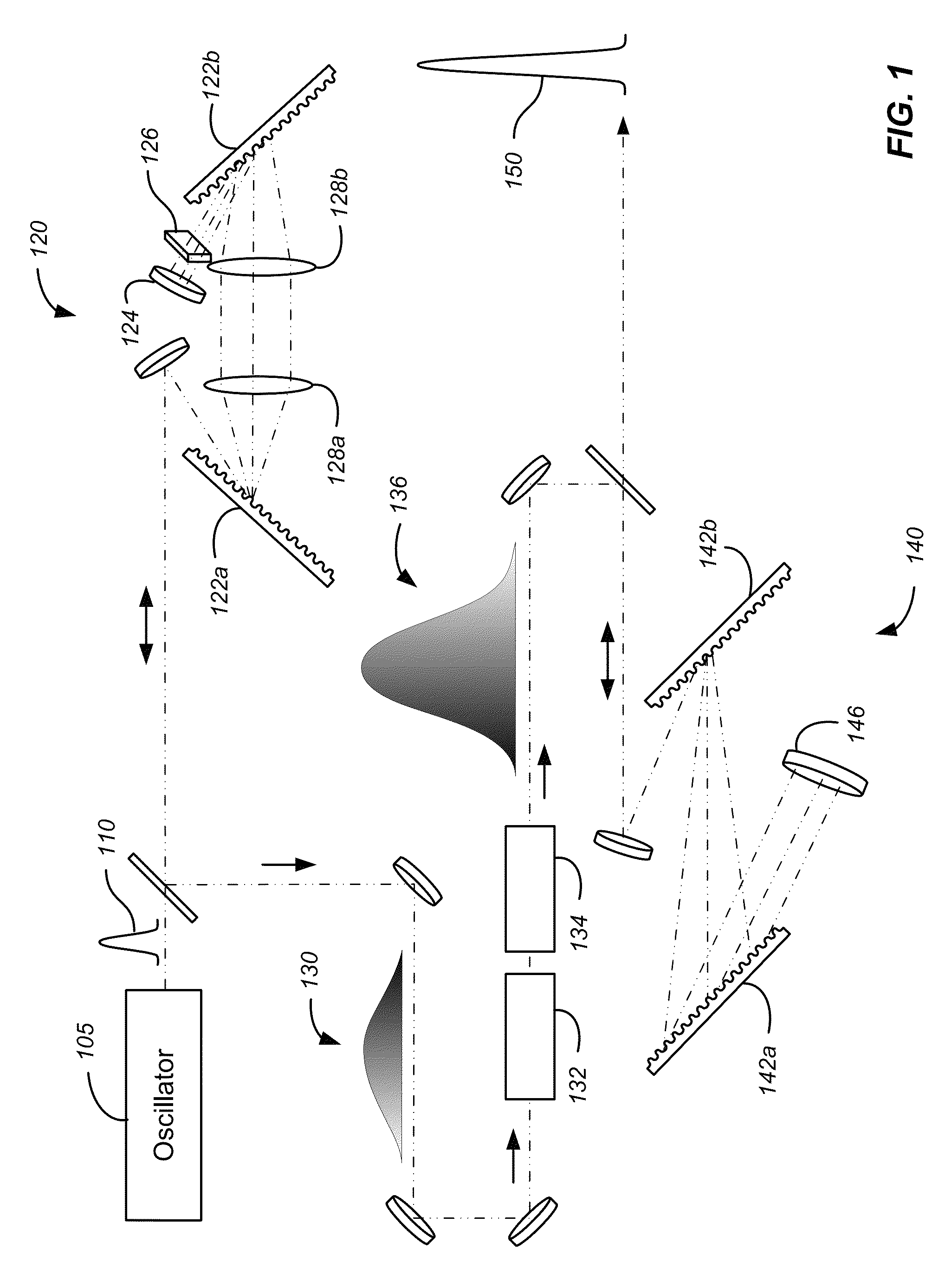
[0019]According to embodiments of the present invention, short pulse generation by chirped pulse amplification utilizes compensation of the dispersion induced by optical materials in the system to achieve a minimum temporal pulse. It will be appreciated that the optical materials present in the system add higher order dispersive terms that are difficult or impossible to compensate with simple angle or distance adjustments to the pulse stretcher or compressor gratings. As discussed above, several techniques have been developed to compensate for these dispersive terms including the use of an acousto-optic programmable dispersive filter and spatial light modulators. Despite the benefits provided by these active dispersion compensation approaches, there is a need in the art for passive methods of providing dispersion compensation in chirped pulse amplifiers.

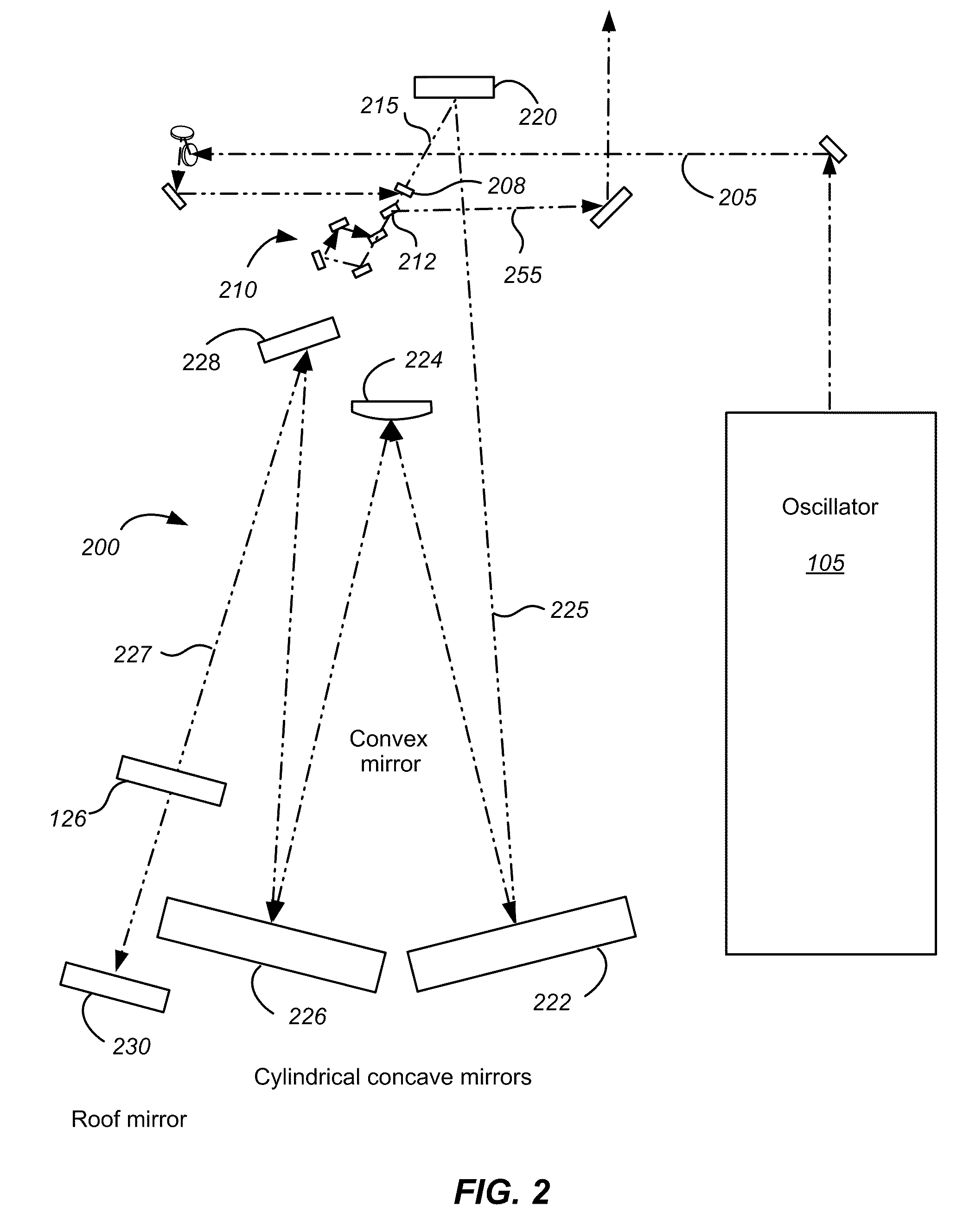
[0020]Embodiments of the present invention utilize magnetorheological finishing (MRF) systems to form predetermined spatial profile...


PUM


Abstract

A chirped pulse amplification system includes a laser source providing an input laser pulse along an optical path. The input laser pulse is characterized by a first temporal duration. The system also includes a multi-pass pulse stretcher disposed along the optical path. The multi-pass pulse stretcher includes a first set of mirrors operable to receive input light in a first plane and output light in a second plane parallel to the first plane and a first diffraction grating. The pulse stretcher also includes a second set of mirrors operable to receive light diffracted from the first diffraction grating and a second diffraction grating. The pulse stretcher further includes a reflective element operable to reflect light diffracted from the second diffraction grating. The system further includes an amplifier, a pulse compressor, and a passive dispersion compensator disposed along the optical path.

Description

CROSS-REFERENCES TO RELATED APPLICATIONS[0001]This application claims priority to U.S. Provisional Patent Application No. 61 / 230,793, filed on Aug. 3, 2009, entitled “Improved optical quality for titanium doped sapphire and sapphire through magnetorheological finishing,” the disclosure of which is hereby incorporated by reference in its entirety for all purposes.STATEMENT AS TO RIGHTS TO INVENTIONS MADE UNDER FEDERALLY SPONSORED RESEARCH OR DEVELOPMENT[0002]The United States Government has rights in this invention pursuant to Contract No. DE-AC52-07NA27344 between the U.S. Department of Energy and Lawrence Livermore National Security, LLC, for the operation of Lawrence Livermore National Laboratory.BACKGROUND OF THE INVENTION[0003]Chirped pulse amplification (CPA) systems are used to amplify ultra-short laser pulses to high power levels. In the CPA system, an input laser pulse is stretched out in time, amplified, and then compresses after amplification. The former Nova laser at the ...

Claims


Application Information

Patent Timeline
Patent Type & Authority Patents(United States)
IPC IPC(8): H01S4/00H01S3/10
CPCH01S3/0057H01S3/005H01S3/2308
Inventor BAYRAMIAN, ANDREW JAMESMOLANDER, WILLIAM A.
Owner LAWRENCE LIVERMORE NAT SECURITY LLC
Why Eureka
Try Eureka