System and method for canceling co-channel interference on-board a satellite

a satellite and cochannel interference technology, applied in the direction of transmission monitoring, orthogonal multiplex, polarisation/directional diversity, etc., can solve the problem that the beam isolation provided by the satellite antenna alone may not always be sufficient to obtain the desired beam, and the total satellite throughput capacity is limited, so as to minimize the effect of cochannel interferen

Inactive Publication Date: 2014-07-15
INTELSAT
View PDF5 Cites 0 Cited by
  • Summary
  • Abstract
  • Description
  • Claims
  • Application Information

AI Technical Summary

Benefits of technology

[0016]One of the objectives of the present application is to introduce methods and systems which allow satellites that support open-network architecture to reuse frequencies in a large number of beams by reducing the co-channel interference between the co-frequency carriers. More than 25 GHz of useful available capacity and more efficient utilization of the satellite's resources are expected for future satellites implementing multi-spot beams and the disclosed methods and systems supporting open-network architecture. Satellites designed to support open network architecture are able to operate with different technologies and terrestrial equipment, whereas the satellites designed to support managed close-network architecture are designed to uses specific techniques and specifics terrestrial equipment.
[0017]Embodiments of the disclosed systems and methods help minimize, using equipment and signal processing on-board a satellite, co-channel interference in signals received at the satellite or signals to be transmitted from the satellite. The co-channel interference is minimized while still allowing for the reduction of the geographic distance between beams or degradation of the satellite antenna quality or a combination of both. This, in turn, results in increased link capacity per satellite and / or the ability to reduce the satellite and / or earth station beam isolation requirements.
[0018]According to an aspect of the present invention, there is provided a method for minimizing co-channel interference on-board a satellite. The method includes post-compensating of an up-link signal received by the satellite. The up-link signal includes a desired signal transmitted by a first transmitter and an interfering signal transmitted by a second transmitter. The post-compensating process includes identifying the interfering signal based on post-compensation parameters including locations of the first transmitter and the second transmitter, carrier power levels of the desired signal and the interfering signal, and satellite antenna characteristics.

Problems solved by technology

Such frequency reuse schemes (e.g., using different polarization or spatial / geographic isolation) increase the overall satellite capacity, as measured by the throughput data rate in bits per second, but also introduce co-channel interference between the signals in the various beams.
For these satellites the beam isolation provided by the satellite antenna alone may not always be sufficient to obtain the desired beam to beam isolation—In addition, uplink level differences for earth stations transmitting in nine or more beams must be considered.
The spatial isolation and the polarization isolation methods utilized in the traditional satellites that support open networks architecture to minimize the impact of the co-channel interference limit the number of beams, and as a consequence limit the total satellite throughput capacity.
This solution also limits the total satellite capacity because, in this case, when one carrier operates at a given frequency in one beam other carriers at the same frequency in the co-channel beams are not allowed to operate.
As a consequence, some of the satellite resources need to be available all the time but are rarely used.

Method used


Image

  • System and method for canceling co-channel interference on-board a satellite
  • System and method for canceling co-channel interference on-board a satellite
  • System and method for canceling co-channel interference on-board a satellite

Examples


Embodiment Construction

[0057]The present invention will now be described more fully with reference to the accompanying drawings, in which exemplary embodiments of the invention are shown.

[0058]In the following description, matrix algebra is used to model and describe operations on signals. Lower case bolded variables, such as r represents signals vectors. Upper case bolded variables, such as R, represents matrices of complex (e.g., having both gain and phase) channel factors.

[0059]It is common for satellites to utilize different uplink and downlink frequencies, and intermediate frequencies within the satellite, which requires frequency shifting operations in the satellites, ground stations and / or both. Such frequency shifts are ignored for the purposes of describing the present invention.

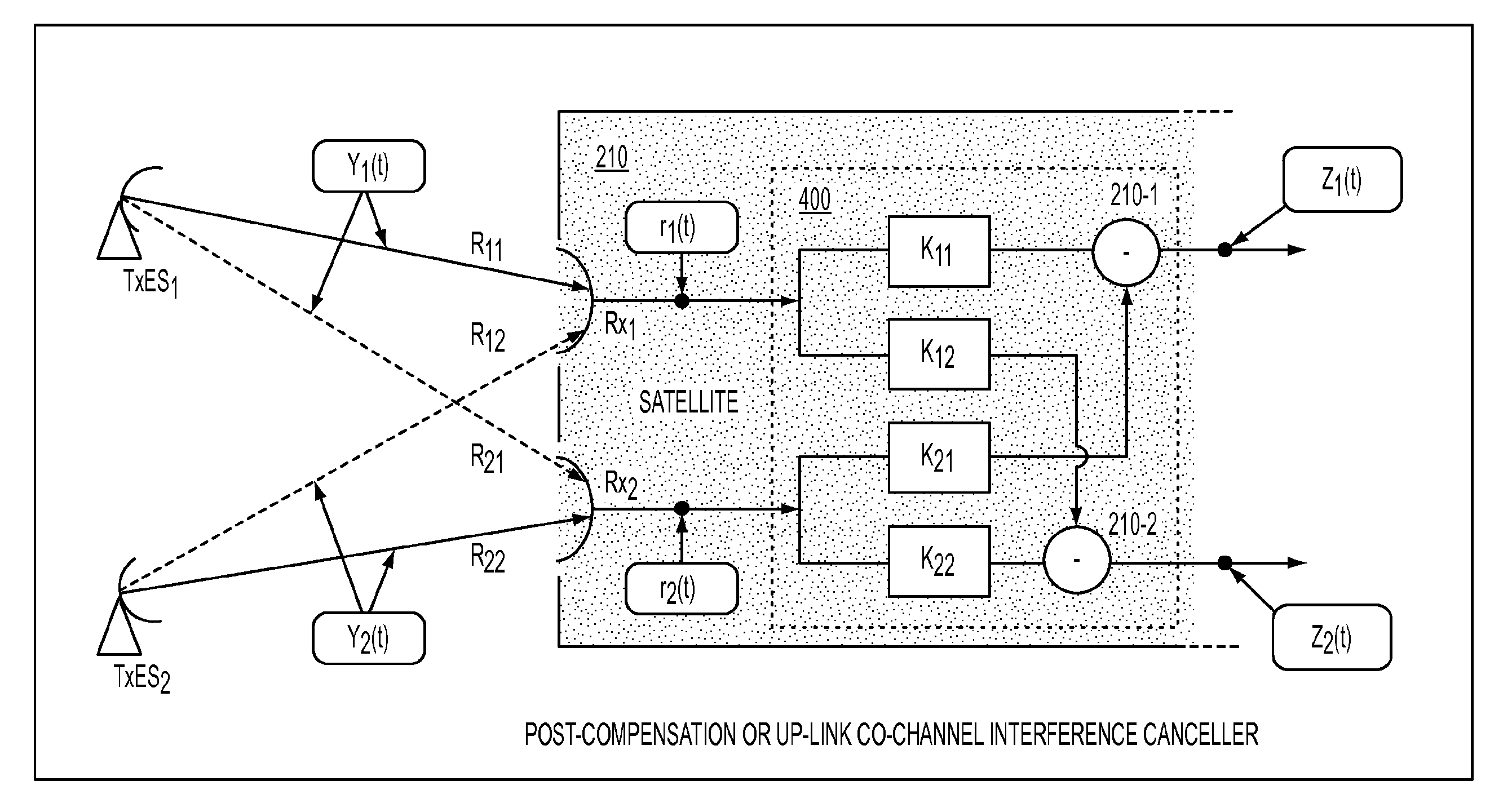
[0060]As illustrated in FIG. 3, one embodiment of the present invention provides a system 200 for canceling co-channel interference, employed on-board a satellite 20, which compensates the co-channel interference arising ...


PUM


Abstract

Provided are systems and methods for minimizing co-channel interference on-board a satellite. An up-link signal received by the satellite is post-compensated, where the up-link signal includes a desired signal transmitted by a first transmitter and an interfering signal transmitted by a second transmitter. The post-compensating includes identifying the interfering signal based on post-compensation parameters. In addition, a down-link signal to be transmitted from the satellite to a receiver is pre-compensated. The pre-compensation process includes determining gain relations between a gain of a first satellite antenna which transmits the down-link in a direction of the receiver and a gain of a second satellite antenna which transmits an interfering signal in the direction of the receiver, sampling and scaling interfering signals at the satellite based on the gain relations, and estimating a co-channel down-link interference component that the down-link signal is expected to experience on a path to the receiver.

Description

CROSS-REFERENCE TO RELATED PATENT APPLICATION[0001]This application is a National Stage of International Application No. PCT / US2012 / 054821, claiming priority from U.S. Provisional Application No. 61 / 533,465 filed on Sep. 12, 2011, the disclosures of which are incorporated herein by reference in their entirety.BACKGROUND[0002]1. Technical Field[0003]The present invention relates to systems and methods for minimizing co-channel interference in signals sent to or received from a satellite, and more particularly, to systems and methods for reducing the co-channel interference on-board a satellite.[0004]2. Description of the Related Art[0005]It is commonplace for communications satellites to receive and transmit signals from and to ground stations in a number of different beam coverage areas, while utilizing the same uplink and / or downlink frequencies. Such frequency reuse schemes (e.g., using different polarization or spatial / geographic isolation) increase the overall satellite capacity...

Claims


Application Information

Patent Timeline
Patent Type & Authority Patents(United States)
IPC IPC(8): H04B7/185
CPCH04B7/18515H04J11/004H04J11/005H04B7/10H04B7/18519
Inventor MORENO, DANIEL
Owner INTELSAT
Why Eureka
Try Eureka