
Method for straightening tube and straightening roll

a technology of straightening roll and tube, which is applied in the direction of metal rolling stand, metal rolling arrangement, manufacturing tools, etc., can solve the problems of deteriorating productivity, requiring complex and highly accurate control, and not being able to straighten the tube end portion, etc., to achieve enhanced straightening effect, reduce the occurrence of leading-end deformation, and reduce the effect of offsetting

Active Publication Date: 2014-07-22
NIPPON STEEL CORP
View PDF19 Cites 5 Cited by
  • Summary
  • Abstract
  • Description
  • Claims
  • Application Information

AI Technical Summary

Benefits of technology

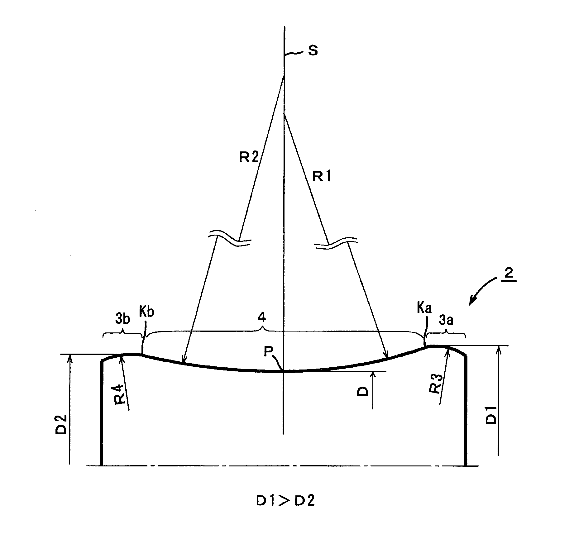
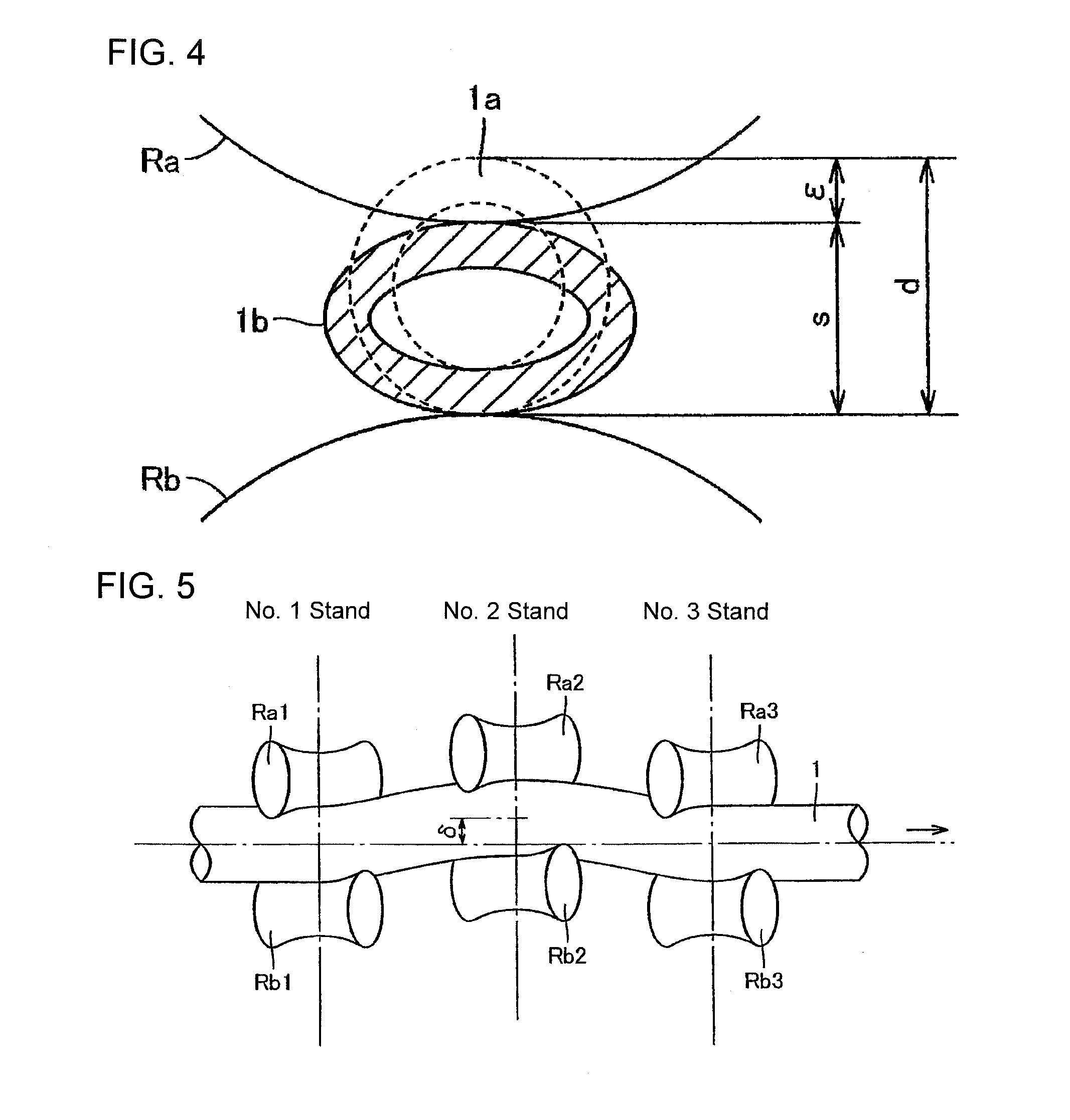
The present invention provides a method for straightening a tube using an asymmetric roll with different diameters at the left and right roll shoulder. This asymmetric roll design prevents leading-end deformation and allows for a larger offsetting of the tube to be straightened, resulting in enhanced straightening effects. The straightening roll is made up of roll shoulders with different diameters and a roll barrel portion with different surfaces. This roll design avoids the collision of the leading end of the tube against the roll, reducing the likelihood of leading-end deformation.

Problems solved by technology

This is caused by that, when a tube is obliged to pass through the straightening rolls which are offset, the front end of the tube is liable to miss the engagement in between the upper and lower rolls, and collides with the rolls, thereby being subjected to an impact.
Since occurrence of leading-end deformation causes the outer diameter to decrease, the affected part must be cut off thereby deteriorating the productivity.
However, in such a method, since the front end of the tube will pass through the straightening roll before crushing is applied, straightening of the tube end portion will not be achieved.
Further, it requires complex and highly accurate control.
On the other hand, although there is a method in which the straightening condition is mitigated such as by setting a smaller offsetting, as well as a method in which the impact between the roll and the tube to be straightened is suppressed by enlarging the roll angle, the straightening force becomes weak in these methods, and thereby the straightening effect declines so that bends in the tube may not be sufficiently removed causing some of them to remain.
If such bends remain, a separate re-straightening processing such as one to remove bends by using a press machine arranged in an off-line, or one to remove bends by passing the tube through the straightener again becomes necessary, thus deteriorating the productivity.

Method used


Image

  • Method for straightening tube and straightening roll
  • Method for straightening tube and straightening roll
  • Method for straightening tube and straightening roll

Examples


example 1

[0078]Straightening of a tube was performed with a carbon steel tube (material corresponding to API standard: X52) having an outer diameter of 34.0 mm and a wall thickness of 2.3 mm as a workpiece by applying the straightening method of the present invention to investigate the effect of suppressing the leading-end deformation of a tube end portion. It is noted that for comparison purpose, similar investigation was conducted for the case where an ordinary symmetric roll was used.

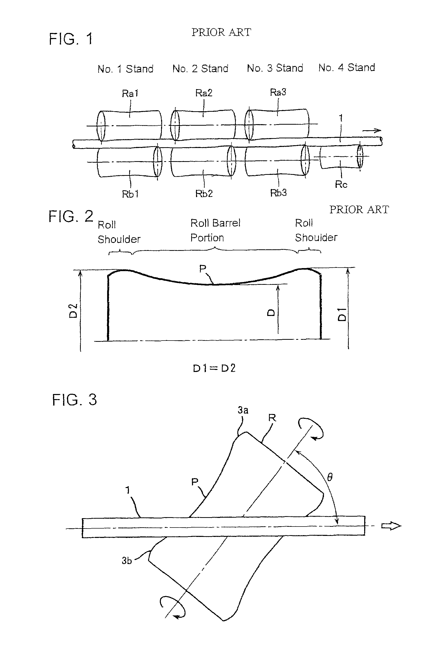
[0079]The straightener used was a 2-2-2-1 type straightener. Table 1 shows roll conditions. The roll condition 1 in Table 1 shows a case where symmetric rolls were used for all stands, and the roll condition 2 shows a case where an asymmetric roll was used for upper and lower rolls of No. 2 stand and No. 3 stand.

[0080]

TABLE 1No. 1No. 2No. 3No. 4StandStandStandStandRollUpperSymmetricSymmetricSymmetric—condi-rollrollrollrolltion 1LowerSymmetricSymmetricSymmetricSymmetricrollrollrollrollrollRollUpperSymmetricAsy...

example 2 to example 4

[0089]In commercial operations, carbon steel tubes (material corresponding to API standard: L80-1) each having an outer diameter of 139.7 mm and a wall thickness of 7.72 mm were straightened by applying the straightening method of the present invention to investigate the straightening rate of tested tubes in which bends had not been sufficiently straightened out and bends remained even after the straightening (rate of bend defective). When performing straightening, taking into consideration of the investigation results obtained in Example 1, test was conducted in advance to set straightening conditions (see Table 4) where leading-end deformation of a tube end portion would not occur. Moreover, for the purpose of comparison, investigation results of the rate of bend defective in an operation (commercial operation) before the present invention was applied, that is, investigation results in the case where symmetric rolls were used to perform straightening are listed as well.

[0090]Table...

example 5

[0100]Straightening of a tube was performed with a carbon steel tube (material corresponding to API standard: L80-1) having an outer diameter of 139.7 mm, a wall thickness of 7.72 mm, and a length of 6000 mm as the workpiece by applying the straightening roll of the present invention to investigate the effect on suppressing the leading-end deformation of a tube end portion after straightening. Furthermore, for comparison purpose, similar investigation was conducted for the case where an ordinary symmetric roll was used. The number of steel tubes subjected to the test was 350.

[0101]The straightener used was a 2-2-2-1 type straightener. Table 7 shows roll conditions and straightening setup conditions (crush amount and offset amount). Inventive Example in Table 7 is the case where an asymmetric roll (CR2 / CR1=1.05 to 1.15, (D1−D2) / d=0.02 to 0.1) was applied to the upper and lower rolls of No. 1 to No. 3 stands. The Comparative Example is the case where a symmetric roll (CR2 / CR1=1.00, (D...


PUM

PropertyMeasurementUnit
thicknessaaaaaaaaaa
outer diameteraaaaaaaaaa
heightaaaaaaaaaa

Abstract

A method for straightening a tube by using an asymmetric roll, which has different diameters D1 (exit side), D2 (entry side) at relative maximum diameter portions, left and right roll shoulder portions, as a straightening roll of a straightener, wherein the roll shoulder having a smaller diameter is disposed to be located on the tube entry side. The straightening roll used therefor comprises roll shoulders 3a and 3b and a roll barrel portion 4, in which D1>D2 and 0.004≦(D1−D2) / d≦0.2 (d: outer diameter of tube to be straightened) are satisfied. Further, an aspect of the invention may define radii of curvatures of entry-side and exit-side shoulder potions in a section of the roll cut along a plane including the roll central axis, or a curve representing an outer surface of the roll barrel portion.

Description

TECHNICAL FIELD[0001]The present invention relates to a method for straightening a tube to correct bends of a tube such as a steel tube along its axial direction and out-of-roundness in its cross section (hereafter, referred to as an “oval shape”). In particular, the present invention relates to a method for straightening a tube, in which the deformation of a tube leading end portion (so-called “leading-end deformation”), which occurs in ordinary straightening method of the tube, can be suppressed to prevent a decline in yield which results from cutting off relevant leading-end deformation portions and can achieve sufficient straightening of the tube; and a straightening roll which can suppress the deformation of a tube leading end portion.[0002]Unless otherwise stated, the definitions of terms in the present invention are as follows.[0003]“Leading-end deformation” refers to a collapse of a tube end portion which is caused by the collision of the leading end of a tube to be straight...

Claims


Application Information

Patent Timeline
Patent Type & Authority Patents(United States)
IPC IPC(8): B21B23/00B21B19/00B21D3/04B21D3/05
CPCB21D3/04B21D3/02
Inventor KUROIWA, YOSHIYUKIKURODA, KOUICHIYAMAKAWA, TOMIO
Owner NIPPON STEEL CORP
Learn More