Tubular member with thermal sleeve liner

a technology of tubular member and thermal sleeve, which is applied in the direction of valve housing, fluid pressure control, instruments, etc., can solve the problems of isolation valves used in this service are subjected to frequent and extreme temperature and pressure cycles, and isolation valves used in this service can suffer from premature etc., to inhibit thermal fatigue stress cracking

Active Publication Date: 2014-07-22
MOGAS IND
View PDF37 Cites 6 Cited by
  • Summary
  • Abstract
  • Description
  • Claims
  • Application Information

AI Technical Summary

Benefits of technology

[0010]In another embodiment, a ball valve isolation method is provided for a rapidly cycling temperature service. The method can include installing the isolation ball valve in a line and cycling operation of the isolation ball valve in service at a temperature swing of at least 250° C. at a frequency of at least one cycle per week, wherein the thermal sleeve liner is effective to inhibit thermal fatigue stress cracking in the end connector. In one embodiment, alternating thermal stresses developed in the tubular member are less than 360 MPa (52 ksi). In another embodiment, peak alternating thermal stresses developed in the tubular member are sufficiently low to achieve a design life of at least 30,000 cycles. In an embodiment, the method can further include servicing the isolation ball valve by removing and replacing the thermal sleeve liner.

Problems solved by technology

In some severe service environments, line isolation valves are subjected to frequent and extreme temperature and pressure cycles as the valve is opened and closed.
Because the valve components have different dimensions, for example where end connectors such as flanges are employed, heat transfer may not be uniform and stresses can develop within the materials of construction, which may lead to premature thermal fatigue stress cracking.
Because components in thermal contact with the hot fluid flow can be asymmetrical and / or have different dimensions such that heat transfer occurs at different rates to produce temperature differences in the materials, isolation valves used in this service can suffer from premature thermal fatigue stress cracking, and can also be subject to erosion due to the abrasive nature of the catalyst particles.

Method used


Image

  • Tubular member with thermal sleeve liner
  • Tubular member with thermal sleeve liner
  • Tubular member with thermal sleeve liner

Examples


example

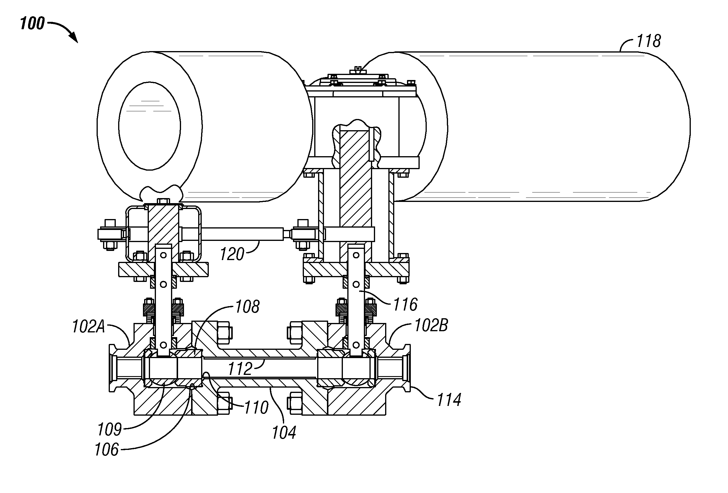
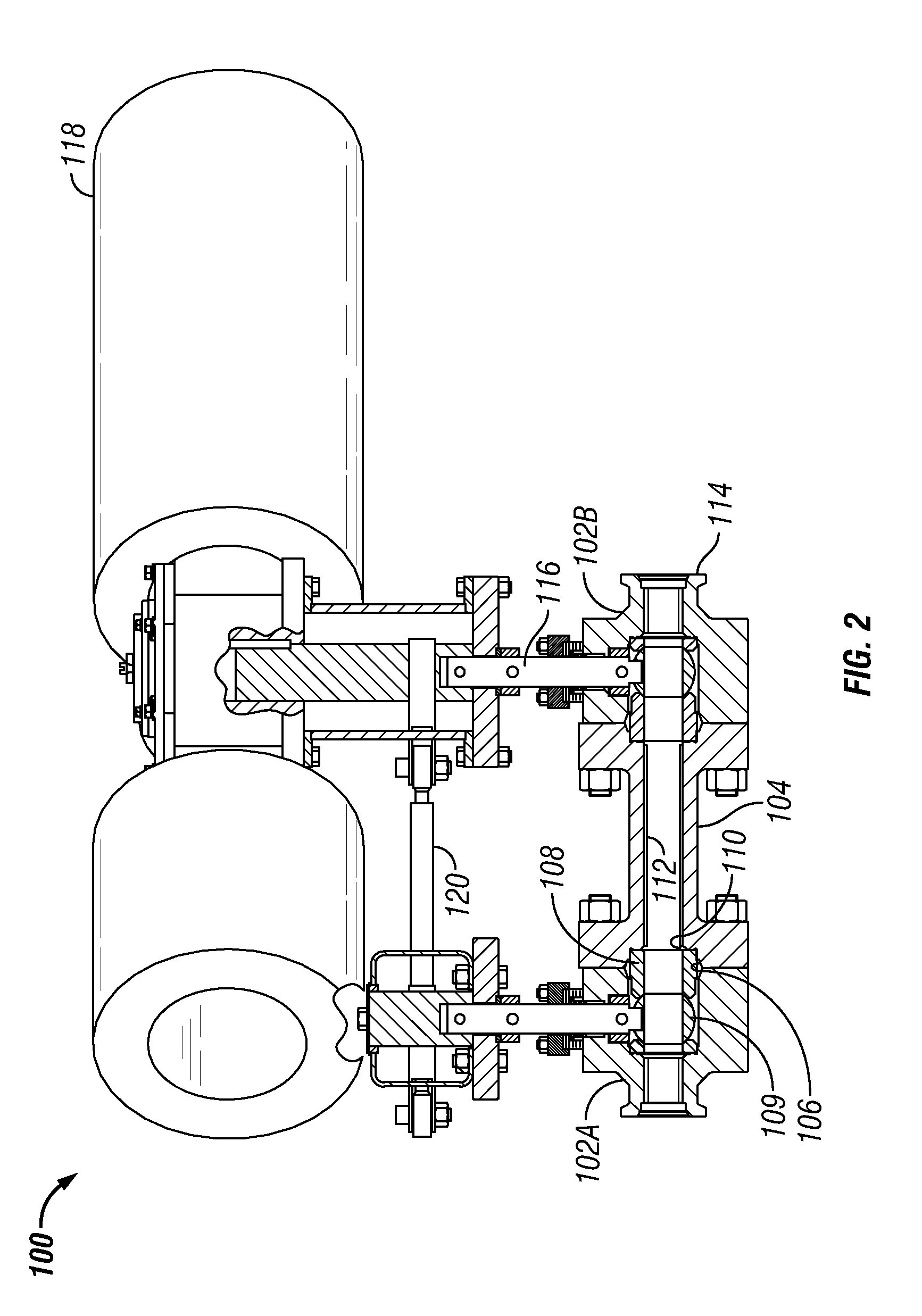
[0030]An isolation ball valve, substantially as shown in FIGS. 2-7 except that it did not use an internal thermal sleeve liner, was used in a catalyst transfer service subjected to extreme pressure and temperature swings between ambient and in excess of 14 MPa and 400° C. on a 10-hour cycle. The end connector 104 had an inside diameter of 58.04 mm (2.285 inches), an outside diameter of 101.6 mm (4 inches) and flanges rated for 17.2 MPa (2500 psi). During shutdown an inspection revealed cracks formed in the interior wall of the end connector, and these were determined to be thermal stress cracking. A finite element analysis using a coupled thermal-pressure transient analysis was performed on a two-dimensional axisymmetric model without the sleeve liner and using a time and grid convergence study. The peak stress intensity in the end connector at the point formed by the inner bore and seat ring cavity was calculated at 841 MPa (122 ksi). Fatigue analysis based on American Society of M...

embodiment 1

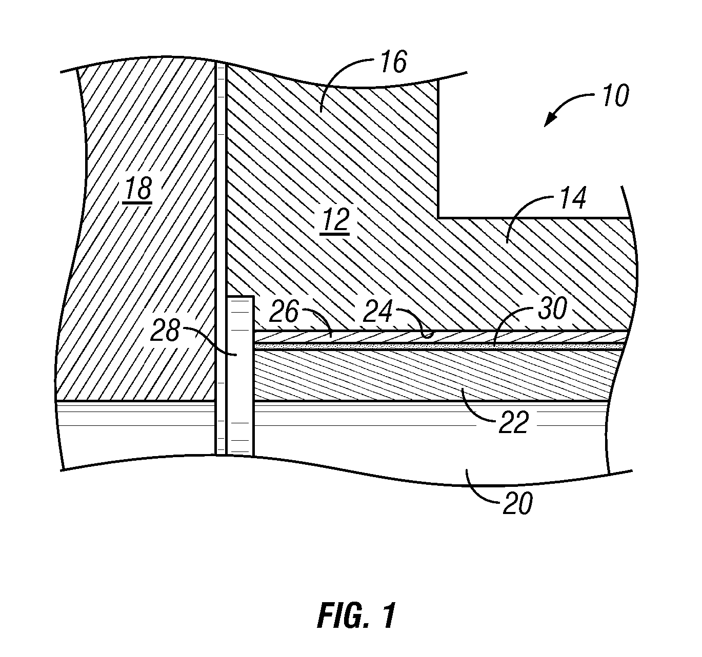
[0033]A tubular fluid flow device of varying outside dimensions for use in a rapidly cycling temperature environment, comprising a tubular member (10) having at least one locus of non-uniform outside dimension (14, 16) and an axial flow passage (20) with a uniform inside diameter between opposite end connection elements (16); a thermal sleeve liner (22) disposed about the axial flow passage in a bore (24) formed in the tubular member, wherein the sleeve comprises an outer surface having a thermal barrier coating (26); and a pressure-relief passage (28) in fluid communication with an interface between an exterior surface of the thermal sleeve liner and an inner surface of the bore.

embodiment 1a

[0034]Embodiment 1 wherein the pressure-relief passage is in fluid communication with the axial flow passage.


PUM

PropertyMeasurementUnit
temperatureaaaaaaaaaa
thermal stressesaaaaaaaaaa
temperaturesaaaaaaaaaa

Abstract

A tubular fluid flow device of varying outside dimensions adapted for use in a high pressure, rapidly cycling temperature environment, an isolation ball valve, a ball valve isolation method and a catalyst transfer method. The flow device 10 can have a tubular member 12 having at least one locus 14, 16 of non-uniform outside dimension and an axial flow passage 20 with a uniform inside diameter between opposite end connection elements. A thermal sleeve liner 22 can be disposed about the axial flow passage in a bore 24 formed in the tubular member, wherein the sleeve comprises an outer surface having a thermal barrier coating 26. A pressure-relief passage 28 is provided in fluid communication between the axial flow passage and an interface between an exterior surface of the thermal sleeve liner and an inner surface of the bore.

Description

CROSS REFERENCE TO RELATED APPLICATION[0001]This application claims the benefit of and priority to provisional application U.S. 61 / 228,442, filed Jul. 24, 2009.BACKGROUND OF THE INVENTION[0002]The present invention relates to tubular fluid flow devices having a varied outer dimension and which are used in high pressure, rapidly cycling temperature environments, and more particularly to such devices employed in severe service metal-seated isolation ball valves, ball valve isolation methods, catalyst transfer, for example, to or from a reactor such as an ebullated bed reactor, and the like.[0003]In some severe service environments, line isolation valves are subjected to frequent and extreme temperature and pressure cycles as the valve is opened and closed. Because the valve components have different dimensions, for example where end connectors such as flanges are employed, heat transfer may not be uniform and stresses can develop within the materials of construction, which may lead to...

Claims


Application Information

Patent Timeline
Patent Type & Authority Patents(United States)
IPC IPC(8): F16L7/00
CPCY10T137/7036H03D3/02F16L59/147F16L23/18F16K27/067Y10T137/87917B23P11/00Y10T137/0508Y10T137/0318Y10T29/49826
Inventor WILLIAMS, JR., JOHN B.NGUYEN, VINHWALKER, JR., JIMMY
Owner MOGAS IND
Why Eureka
Try Eureka