Flexible battery and method for producing the same

a flexible battery technology, applied in the field of flexible batteries, can solve the problems of limiting the improvement of flexibility of the battery, low stretchability of the laminated film, and affecting so as to improve the sealing reliability of the flexible battery, reduce the discomfort caused by the rigidity of the battery, and the effect of high flexibility

Inactive Publication Date: 2014-07-22
PANASONIC CORP
View PDF16 Cites 60 Cited by
  • Summary
  • Abstract
  • Description
  • Claims
  • Application Information

AI Technical Summary

Benefits of technology

[0021]According to the present invention, it is possible to impart high flexibility to a flexible battery including a housing with flexibility, as well as to improve the sealing reliability of the flexible battery. As a result, for example, in the case where the present invention is applied to a battery used for a patch-type supplying device that operates while a battery serving as a power supply is in contact with a living body, the discomfort caused by the rigidity of the battery can be reduced. In addition, the battery is excellent not only in flexibility but also in sealing reliability, and therefore, leakage of electrolyte and the like will not occur, allowing for long-term storage or use of the device.

Problems solved by technology

However, this feature could be an obstacle to making the battery more flexible and thinner.
Such a laminated film is low in stretchability.
Using it as it is for a housing of a battery will limit the improvement in flexibility of the battery.
Moreover, if such a laminate housing with low stretchability is forcibly bent, the housing may rupture or break.
The rupture or breakage of the laminate housing, if any, may result in evaporation of the electrolyte or deterioration in battery performance.

Method used


Image

  • Flexible battery and method for producing the same
  • Flexible battery and method for producing the same
  • Flexible battery and method for producing the same

Examples


embodiment 1

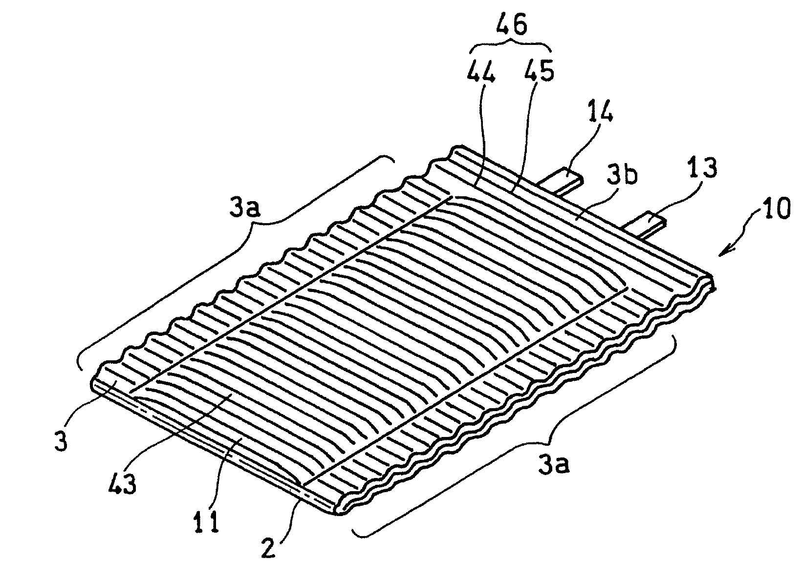
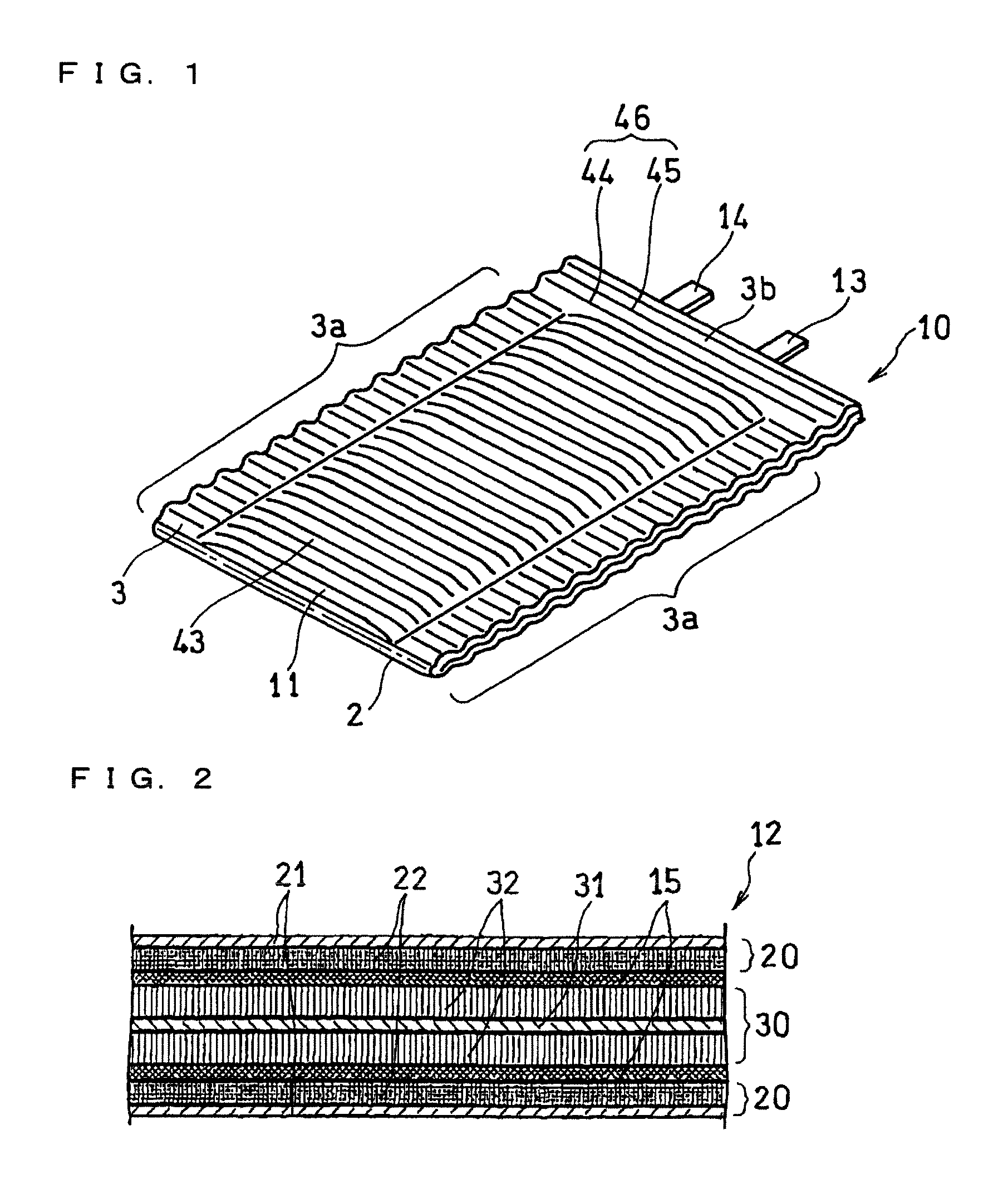
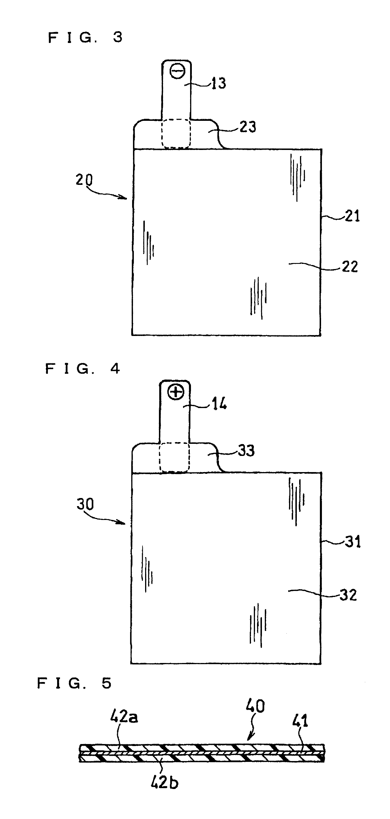
[0065]FIG. 1 is an oblique view of the appearance of a flexible battery produced by the production method of a flexible battery according to one embodiment of the present invention. FIG. 2 is a partial cross-sectional view of an exemplary electrode group included in the battery of FIG. 1. FIGS. 3 and 4 are plane views of exemplary positive electrode and negative electrode included in the electrode group. FIG. 5 is a partial cross-sectional view of the structure of a laminated film being an exemplary material for a housing.

[0066]A flexible battery (hereinafter simply referred to as a “battery”) 10 illustrated in the figure includes: a sheet-like electrode group 12 obtained by stacking a sheet-like negative electrode 20 and a sheet-like positive electrode 30 with an electrolyte layer (a sheet-like separator impregnated with electrolyte) 15; and a housing 11 hermetically enclosing the electrode group 12. The shape of the battery 10 may be flat-plate like or curved-plate like. Although ...

embodiment 2

[0116]Next, Embodiment 2 of the present invention is described with reference to the appended drawings.

[0117]FIG. 16 is a plane view of a laminated film used in the production method of a flexible battery, according to Embodiment 2 of the present invention.

[0118]As illustrated in FIG. 16, in this embodiment, both end areas of the rectangular laminated film 40 in its longitudinal direction, that is, areas corresponding to the parallel section 3b of the bonded portion 3 (the bonding margins 47) are not formed in the corrugated shape and are formed as flat areas 48. The other area of the laminated film 40 is formed in the corrugated shape 46 including the ridge and valley lines 44 and 45, as in Embodiment 1. In the middle of the laminated film 40 in its longitudinal direction, the fold line 2 parallel to the ridge and valley lines 44 and 45 is formed at such a position that the corrugated shape 46 in one of the bonding margins 47 becomes in phase with that of the other, as in Embodimen...

embodiment 3

[0121]Next, Embodiment 3 of the present invention is described with reference to the appended drawings.

[0122]FIG. 20 is a plane view of a schematic configuration of a laminated film used in the production method of a flexible battery, according to one embodiment of the present invention.

[0123]As illustrated in FIG. 20, in the laminated film 40 of this embodiment also, both end areas of the rectangular laminated film 40 in its longitudinal direction are not formed in the corrugated shape. Specifically, of the two bonding margins 47, portions corresponding to the parallel section 3b of the bonded portion 3 are not formed in the corrugated shape, and formed as the flat areas 48. In this embodiment, however, of the two bonding margins 47, areas corresponding to the perpendicular sections 3a are also not formed in the corrugated shape, and formed as flat areas 49. Only areas corresponding to the two facing portions 43 of the laminated film 40 are formed in the corrugated shape 46 includi...


PUM

PropertyMeasurementUnit
widthaaaaaaaaaa
widthaaaaaaaaaa
widthaaaaaaaaaa

Abstract

Disclosed is a flexible battery including a sheet-like electrode group, an electrolyte, and a housing with flexibility enclosing the electrode group and electrolyte. The housing includes a film material folded into two in which the electrode group is inserted. The film material has two facing portions respectively facing two principal surfaces of the electrode group, a fold line which is between the two facing portions and along which the film material is folded, and two bonding margins respectively set around the two facing portions. The two bonding margins are bonded to each other into a bonded portion. At least the two facing portions of the film material are formed in a corrugated shape having a plurality of ridge and valley lines arranged in parallel to each other. The ridge lines in one of the two facing portions are overlapped with the valley lines in the other. The fold line is parallel to the ridge and valley lines.

Description

RELATED APPLICATIONS[0001]This application is the U.S. National Phase under 35 U.S.C. §371 of International Application No. PCT / JP2011 / 007052, filed on Dec. 16, 2011, which in turn claims the benefit of Japanese Application No. 2011-087036, filed on Apr. 11, 2011, the disclosures of which Applications are incorporated by reference herein.TECHNICAL FIELD[0002]The present invention relates to a flexible battery including a housing made of a film-like material, and a method for producing the same.BACKGROUND ART[0003]The recent spread of portable electronic devices with compact design such as cellular phones and hearing aids is remarkable.[0004]Devices that operate in contact with the skin of a living body also get more varied and spread. For example, a vital sign remote monitoring device that measures or monitors vital signs, such as body temperature, blood pressure, and pulse, and automatically transmits the obtained information to a hospital and the like has been developed. A patch-t...

Claims


Application Information

Patent Timeline
Patent Type & Authority Patents(United States)
IPC IPC(8): H01M10/04H01M10/052H01M10/0583H01M2/02H01M6/00H01M10/058H01M50/105H01M50/124H01M50/136H01M50/178H01M50/55H01M50/553H01M50/562H01M50/566
CPCH01M10/0583H01M10/0436H01M2/021H01M2/02H01M10/052H01M2/026Y02E60/122H01M2/0287H01M2/0275H01M2/0285H01M2/0277H01M10/058Y10T29/49108Y02P70/50Y02E60/10H01M50/124H01M50/553H01M50/178H01M50/105H01M50/55H01M50/566H01M50/136H01M50/562
Inventor UEDA, TOMOHIRO
Owner PANASONIC CORP
Why Eureka
Try Eureka