Electric machine and oil cooling method for electrical machine

a technology of electric machines and winding coils, which is applied in the direction of dynamo-electric machines, electrical apparatus, windings, etc., can solve the problems of uneven cooling on every winding coil, difficulty in mounting and manufacturing these grooves, and the loss of cooling oil pressure, so as to improve the thermal durability of the electrical machine and improve the cooling efficiency of the winding coils

Active Publication Date: 2014-07-22
JING JIN ELECTRIC TECH CO LTD
View PDF15 Cites 6 Cited by
  • Summary
  • Abstract
  • Description
  • Claims
  • Application Information

AI Technical Summary

Benefits of technology

[0008]The present invention also provides an electrical machine, which can cool its own winding coils more effectively and increase its thermal durability.
[0009]The present invention also provides an oil cooling method for electrical machine, which can cool the winding coils of the electrical machine more effectively such that the electrical machine has a high thermal durability.
[0032]It can be seen from the above technical solution that the technical solution of the present invention, i.e., providing oil-guides between the oil outlet holes and the winding coils of the electrical machine, and guiding cooling oil flowing out of the oil outlet holes by the oil-guides to pour onto the winding coils when the cooling oil enters from the oil inlet hole, flows through the oil passage and then flows out of the oil outlet holes, avoids the loss of the cooling oil along the circumferential wall of the housing and the casing end cover due to surface tension after the cooling oil flows out of the oil outlet holes, and allows the cooling oil to pour directly on the winding coils such that the winding coils can be evenly cooled. This greatly enhances the cooling efficiency of the winding coils of the electrical machine, thereby improving the thermal durability of the electrical machine.

Problems solved by technology

In most of the oil passage designs for cooling winding coils in the electrical machine, there are often a number of 90-degree corners in the oil passage from the oil inlet hole to the oil outlet hole, causing the cooling oil to lose pressure.
However, it is not easy to mount and manufacture these grooves, especially to ensure that the coils should not be touched when mounting the grooves so as to prevent from destroying the insulation of the coils.
This leads to uneven cooling on every winding coil.
In conclusion, the cooling efficiency is not high in the existing solutions for cooling the winding coils of the electrical machine, leading to poor thermal durability of the electrical machine.

Method used


Image

  • Electric machine and oil cooling method for electrical machine
  • Electric machine and oil cooling method for electrical machine
  • Electric machine and oil cooling method for electrical machine

Examples


first embodiment

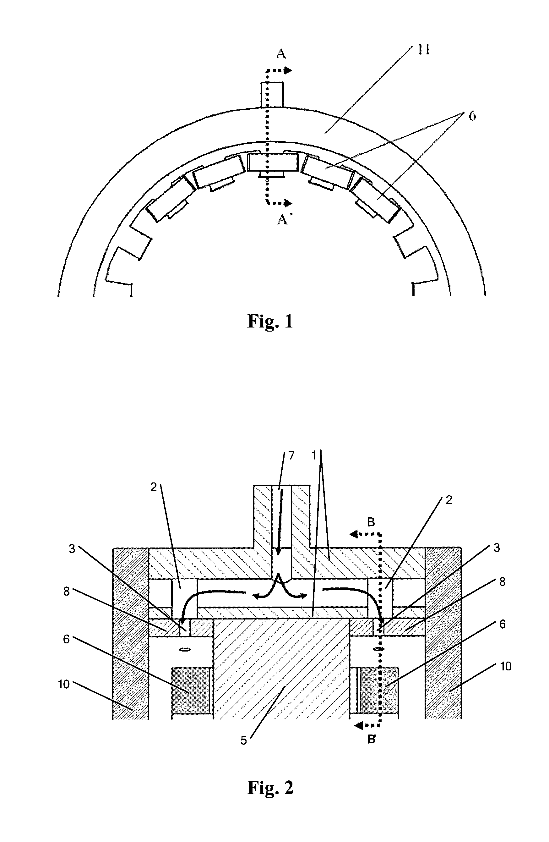
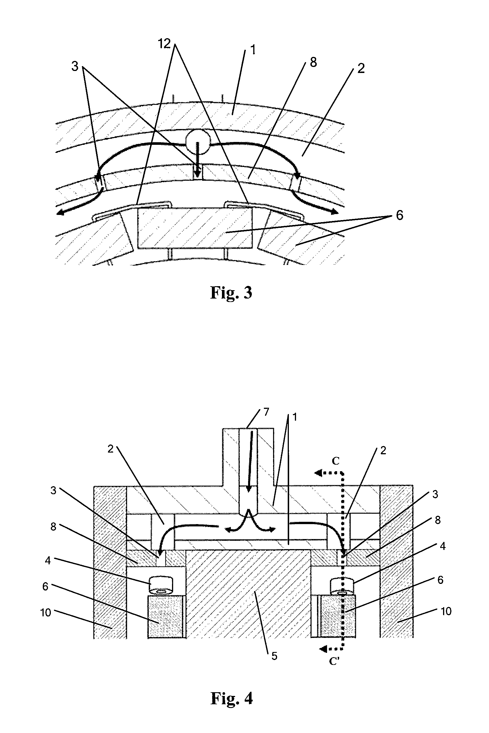
[0047]FIG. 4 is a schematic diagram of the electrical machine in the present invention. FIG. 4 is a sectional view taken along a line AA′ shown in FIG. 1. Referring to FIG. 4, the electrical machine comprises: a housing and a stator assembly. Wherein the housing comprises: a casing 1, an oil inlet hole 7, an oil passage 2, oil outlet holes 3, a stator retainer 8 and a casing end cover 10; wherein the oil inlet hole 7 is located in the casing 1, the oil outlet holes 3 are located in the stator retainer 8, and the oil passage 2 is located inside the casing 1 and links with the oil inlet hole 7 and the oil outlet holes 3. The stator assembly comprises: a stator iron core 5, winding coils 6 and slot insulations 12; here, the slot insulations 12 cannot be seen in the sectional view of FIG. 4, but the position thereof will be shown in the succeeding FIG. 5; the oil outlet holes 3 are located above the winding coils 6. The above structure is the same with the prior art.

[0048]In the embodim...

second embodiment

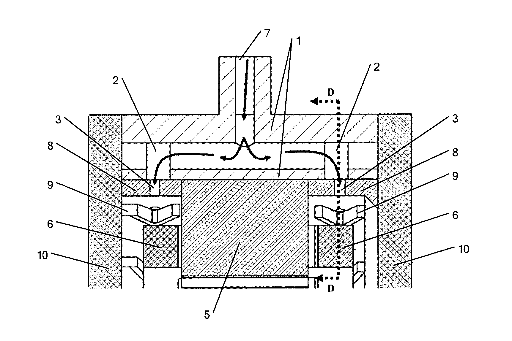
[0053]FIG. 6 is a schematic diagram of the electrical machine in the present invention. FIG. 6 is a sectional view taken along a line AA′ shown in FIG. 1. Referring to FIG. 6, the electrical machine comprises: a housing and a stator assembly. Wherein the housing comprises: a casing 1, an oil inlet hole 7, an oil passage 2, oil outlet holes 3, a stator retainer 8 and a casing end cover 10; wherein the oil inlet hole 7 is located in the casing 1, the oil outlet holes 3 are located in the stator retainer 8, and the oil passage 2 is located inside the casing 1 and links with the oil inlet hole 7 and the oil outlet holes 3. The stator assembly comprises: a stator iron core 5, winding coils 6 and slot insulations 12; here, the slot insulations 12 cannot be seen in the sectional view of FIG. 6, but the position thereof will be shown in the succeeding FIG. 8; the oil outlet holes 3 are located above the winding coils 6. The above structure is the same with the prior art.

[0054]In the embodim...


PUM

PropertyMeasurementUnit
electrical machineaaaaaaaaaa
shapeaaaaaaaaaa
hole diametersaaaaaaaaaa

Abstract

An electrical machine including a casing (1), an oil inlet hole (7), an oil passage (2), oil outlet holes (3), a stator retainer (8), a casing end cover (10), a stator iron core (5), winding coils (6), slot insulations (12) and oil-guides (4). The oil passage (2) is located inside the casing (1) and links with the oil inlet hole (7) of the casing (1) and the oil outlet holes (3) of the stator retainer (8). The oil outlet holes (3) are located above the winding coils (6) and the oil-guides (4) are located between the oil outlet holes (3) and the winding coils (6). Oil entering from the oil inlet hole (7) pours onto the winding coils (6) by the guidance of the oil-guides (4) after flowing through the oil passage (2) and flowing out of the oil outlet holes (3). The winding coils of the electrical machine can be effectively cooled and the electrical machine can achieve higher thermal durability. An oil cooling method for the electrical machine is also provided.

Description

FIELD OF THE INVENTION[0001]The present invention relates to technology of mechanical manufacture and in particular, an electrical machine and an oil cooling method for electrical machine.BACKGROUND OF THE INVENTION[0002]In the prior art, winding coils in the electrical machine are cooled with cooling oil. In most of the oil passage designs for cooling winding coils in the electrical machine, there are often a number of 90-degree corners in the oil passage from the oil inlet hole to the oil outlet hole, causing the cooling oil to lose pressure. Thus, the cooling oil will not be sprayed onto the winding coils from the oil outlet hole but naturally flow out by gravity.[0003]FIG. 1 is a schematic diagram of the housing and stator assembly of the electrical machine in the prior art. As shown in FIG. 1, a number of winding coils 6 are arranged along the internal arc line of the housing 11 of the electrical machine. FIG. 1 does not show a casing end cover.[0004]FIG. 2 is a sectional view ...

Claims


Application Information

Patent Timeline
Patent Type & Authority Patents(United States)
IPC IPC(8): H02K9/20
CPCH02K9/19H02K9/197Y10T29/49009
Inventor CAI, WEIZHENG, YIYUAN, XINGLIAN
Owner JING JIN ELECTRIC TECH CO LTD
Why Eureka
Try Eureka