Optical electrical hybrid cable

a hybrid cable and optical cable technology, applied in the field of optical cables, can solve the problems of increasing labor, materials, space, and labor costs, and achieve the effects of reducing the external diameter of the cable, and ensuring the effect of optical fiber protection

Inactive Publication Date: 2014-07-29
SAMSUNG ELECTRONICS CO LTD
View PDF16 Cites 240 Cited by
  • Summary
  • Abstract
  • Description
  • Claims
  • Application Information

AI Technical Summary

Benefits of technology

[0012]Aspects of exemplary embodiments of the present invention are to address at least the above-mentioned problems and / or disadvantages and to provide at least the advantages described below. Accordingly, an aspect of exemplary embodiments of the present invention is to provide an optical electrical hybrid cable configured to simultaneously transmit optical signals and electrical signals with one cable efficiently and stably. Benefits of such an aspect of exemplary embodiments of the present invention may include eliminating the need to install fiber-optic cables and power cables separately, facilitating addition of fiber-optic units, reducing the external diameter of the cable, and protecting optical fibers effectively from the force exerted from the outside such as external tension and external shocks.

Problems solved by technology

Conventionally, fiber-optic cables and power cables are installed separately, thereby causing the need for wide cable installation spaces and the delay in installation work.
Such installation methods according to the related art have increased costs associated with labor, materials, and space.
Disadvantageously, however, for a cable with such a configuration, it is difficult to separate fiber-optic units and power cables, add optical fibers, and protect optical fibers from external forces such as external tension and external shocks that may be exerted on the cable.
Further, in a cable with such a configuration, in order to insert fiber-optic tubes into a valley between power cables, the power cables must be considerably large in diameter, thereby causing restrictions on the reduction in diameter of the cable.

Method used


Image

  • Optical electrical hybrid cable
  • Optical electrical hybrid cable
  • Optical electrical hybrid cable

Examples


Embodiment Construction

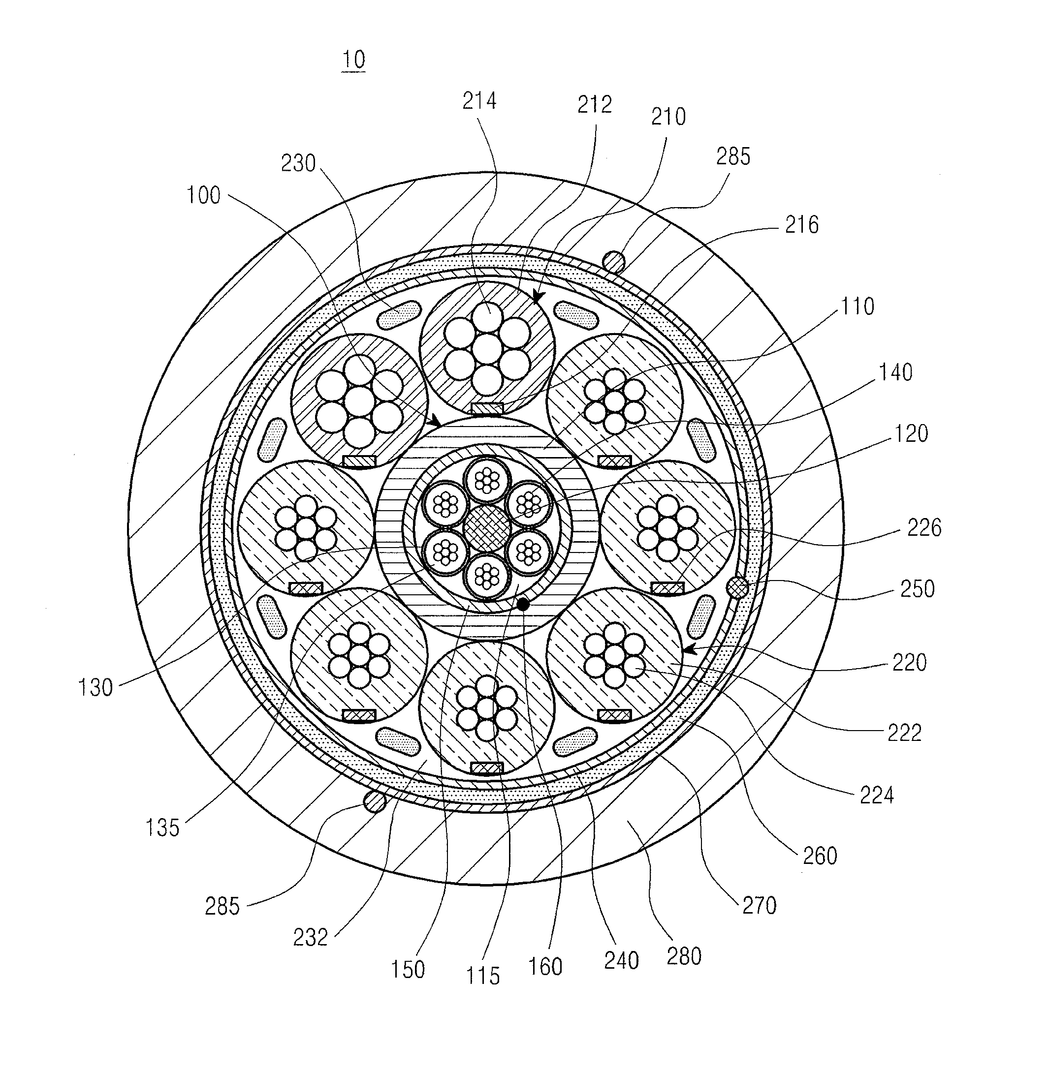
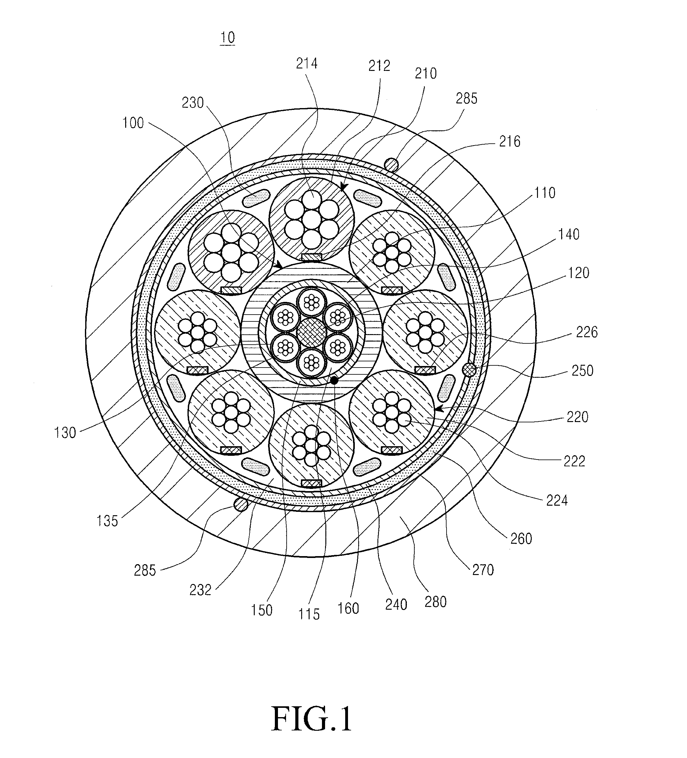
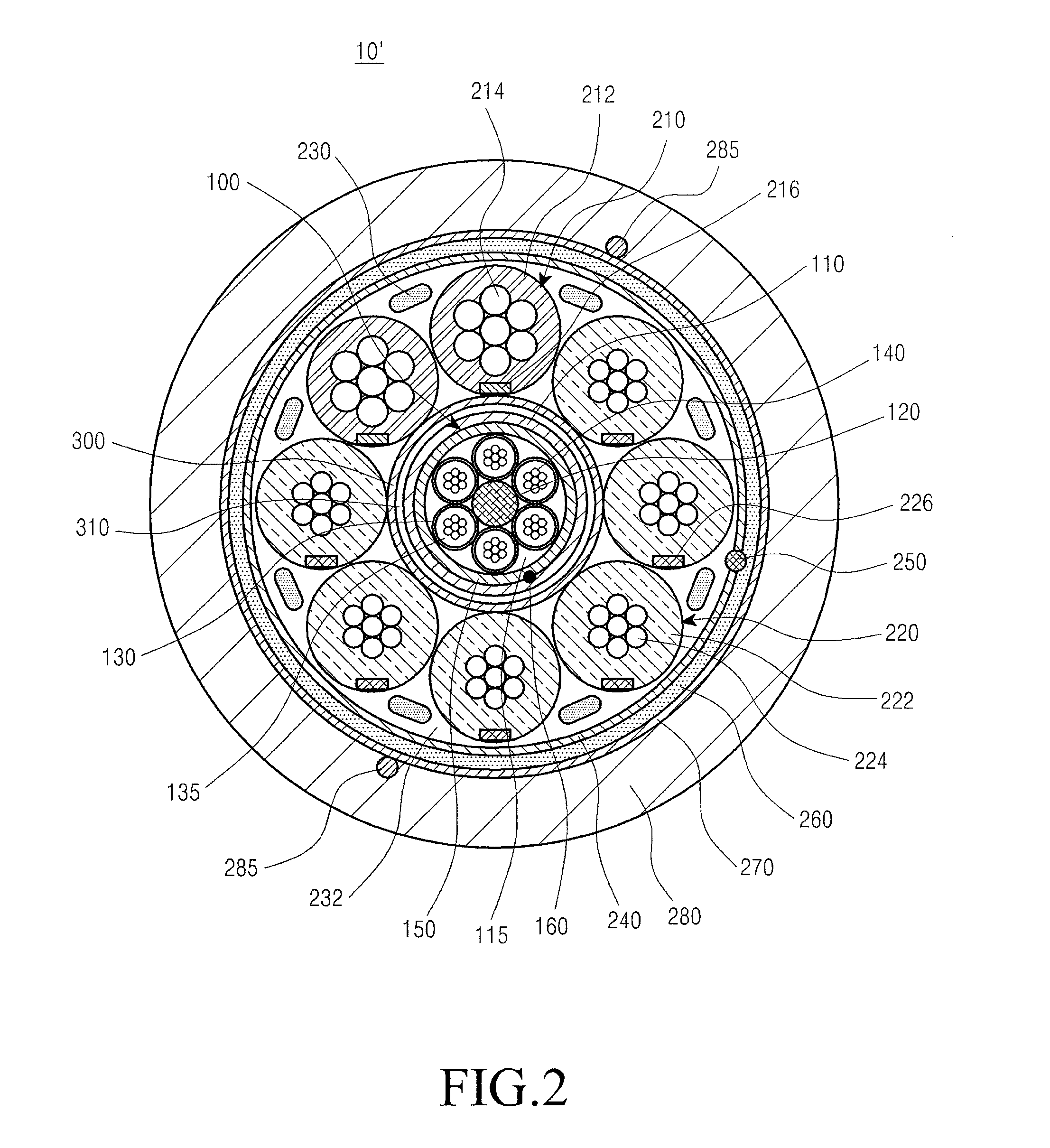
[0021]The following description with reference to the accompanying drawings is provided to assist in a comprehensive understanding of exemplary embodiments of the invention as defined by the claims and their equivalents. It includes various specific details to assist in that understanding but these are to be regarded as merely exemplary. Accordingly, those of ordinary skill in the art will recognize that various changes and modifications of the embodiments described herein can be made without departing from the scope and spirit of the invention. In addition, descriptions of well-known functions and constructions may be omitted for clarity and conciseness.

[0022]The terms and words used in the following description and claims are not limited to the bibliographical meanings, but, are merely used by the inventor to enable a clear and consistent understanding of the invention. Accordingly, it should be apparent to those skilled in the art that the following description of exemplary embod...


PUM

PropertyMeasurementUnit
diameteraaaaaaaaaa
diameteraaaaaaaaaa
cross-sectional areaaaaaaaaaaa

Abstract

An optical electrical hybrid cable for transmitting an optical signal and an electrical signal simultaneously is provided. The optical electrical hybrid cable includes a fiber-optic cable disposed in the center of the optical electrical hybrid cable, and including a plurality of tubes each of which comprises a plurality of optical fibers operatively mounted in an inner space thereof, and a first binder disposed around the plurality of tubes, a plurality of power cables disposed around the fiber-optic cable, each of the power cables comprising a plurality of conducting wires, and a second binder disposed around the plurality of power cables.

Description

PRIORITY[0001]This application claims the benefit under 35 U.S.C. §119(a) of a Korean patent application filed in the Korean Intellectual Property Office on May 3, 2011 and assigned Serial No. 10-2011-0041847, the entire disclosure of which is hereby incorporated by reference.BACKGROUND OF THE INVENTION[0002]1. Field of the Invention[0003]The present invention relates generally to an optical cable. More particularly, the present invention relates to an optical electrical hybrid cable capable of simultaneously transmitting optical signals and electrical signals.[0004]2. Description of the Related Art[0005]Due to the industrial development, the amount of information required by users has increased exponentially. Such an exponential increase in the amount of information to be communicated over communication networks has led to the advent of the Fiber-To-The-Home (FTTH) era in which optical cables will reach inside buildings to increase throughput of the information dramatically.[0006]C...

Claims


Application Information

Patent Timeline
Patent Type & Authority Patents(United States)
IPC IPC(8): H01B11/22G02B6/42
CPCG02B6/4416G02B6/441H01B11/22
Inventor CHOI, HAN-DONGLEE, HO-SOON
Owner SAMSUNG ELECTRONICS CO LTD
Why Eureka
Try Eureka